
7 Best Automatic Arc Welding Machines for 2026?
Choosing the right Automatic Arc Welding Machine is a production decision, not just a search for the highest speed. The International Federation of Robotics’ World Robotics 2024 report recorded 541,302 industrial robot installations worldwide in 2023. It also counted 4,281,585 industrial robots in operation. These figures cover many industries, not welding alone, but they show how widely factory automation is being adopted.
For welding shops, the practical questions are more specific. Can a system hold a steady arc on the intended material and joint? Does its control package suit the operator, and can it fit the cell, fixtures, and extraction setup? A polished specification sheet cannot answer every question. Fit matters. So do service access, consumable availability, and the quality of test welds made on your own parts.
This guide compares seven automatic arc welding machines for 2026, focusing on capabilities that affect real production: process compatibility, controls, integration, and support. Models vary, and published specifications may not reveal performance on a particular job. Treat the shortlist as a starting point, then verify claims with current manufacturer documentation and a representative weld trial. Automation can improve repeatability. It cannot fix poor joint preparation or a mismatched process. That part is easy to overlook. A ranking can simplify a complicated purchase, so the best choice still depends on your materials, volumes, and shop conditions.
How Automatic Arc Welding Machines Work
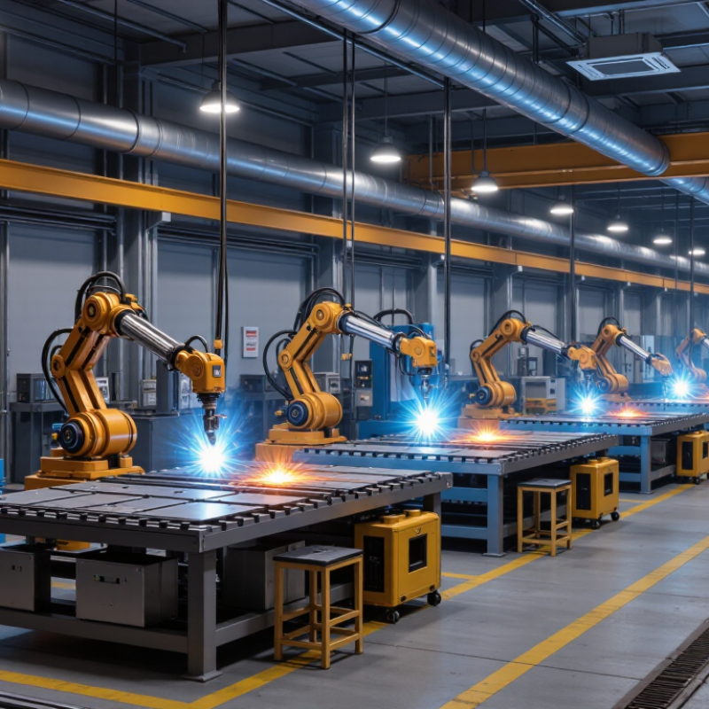
Automatic arc welding machines create a controlled electrical arc between an electrode and the workpiece. The arc’s heat melts the joint edges and, in many processes, filler metal from a continuously fed wire. A power source regulates current and voltage, while a torch or welding head follows a programmed path. Shielding gas helps protect the molten pool from contamination. Small changes matter.
During a cycle, sensors and controls can monitor variables such as wire-feed speed, travel speed, and arc voltage. Some systems adjust settings when the arc shifts; others mainly repeat a fixed path, so setup quality remains essential. The International Federation of Robotics’ World Robotics 2024 report recorded 541,302 industrial robot installations worldwide in 2023, up 10% from 2022. This covers many industries, not welding alone, but illustrates the wider move toward automated production. Automation improves repeatability, yet it cannot guarantee a sound weld when fit-up, surface condition, or programming is poor.
Tips: Clean the joint, confirm the correct wire and shielding gas, and test the path on sample material. Watch the first passes closely. A neat-looking bead can still hide a problem, so inspect the weld and verify machine settings rather than trusting appearance alone.
| No. | Automatic machine type | Arc welding process | Typical operating range* | How automation works | Best suited for | Key selection consideration |
|---|---|---|---|---|---|---|
| 1 | Mechanized wire-feed carriage | Gas metal arc welding (GMAW/MIG) | About 200–500 A; commonly 0.8–1.6 mm solid wire | A powered carriage moves the torch along a joint while the feeder supplies wire and shielding gas. | Long, straight fillet and butt welds on frames, tanks, and structural parts | Check whether the carriage can maintain torch angle and travel speed on the intended joint. |
| 2 | Robotic welding cell | Primarily GMAW; also flux-cored arc welding (FCAW) | Commonly about 200–500 A; wire size and duty cycle depend on the power source and job | A programmed robot controls torch position and motion; sensors or fixtures help locate and repeat the weld path. | High-volume, repeatable production of components with consistent joint geometry | Account for programming, fixturing, safety guarding, part variation, and maintenance—not just the robot. |
| 3 | Mechanized FCAW seam system | Flux-cored arc welding (FCAW) | Often about 250–600 A; wire diameters around 1.2–2.4 mm are common in production work | A tractor, gantry, or positioner guides a continuously fed tubular electrode along the seam. | Heavy fabrication, structural assemblies, and welds where FCAW’s deposition rate is useful | Confirm the wire type, shielding requirements, position, and slag-removal access for the application. |
| 4 | Submerged-arc welding (SAW) tractor | Submerged-arc welding (SAW) | Commonly about 300–1,000 A and 28–44 V, depending on electrode and setup | A tractor feeds the electrode and granular flux while traveling along the joint; the arc is covered by flux. | Long, mostly flat or horizontal seams in plate, beams, vessels, and pipe fabrication | SAW generally needs suitable joint access, flux handling, and a position that keeps the flux over the arc. |
| 5 | Tandem SAW system | Multi-electrode submerged-arc welding | Often uses two or more arcs; approximately 400–1,000 A per arc is a representative range | Multiple wire electrodes weld in sequence or together to increase deposition and travel capability. | Thick plate and long production seams where high deposition rates justify a more complex setup | Requires careful coordination of power sources, electrode spacing, flux, and procedure qualification. |
| 6 | Orbital tube-welding head | Gas tungsten arc welding (GTAW/TIG) | Typically about 5–300 A; actual current depends on tube size, wall thickness, and weld cycle | A rotating weld head travels around a fixed tube while a controller manages the welding cycle and, where fitted, filler-wire feed. | Repeatable circumferential tube and pipe welds in clean manufacturing environments | Match the head, clamping system, and programming to tube diameter, wall thickness, and material. |
| 7 | Mechanized plasma-arc welding system | Plasma arc welding (PAW) | Usually a specialized lower-to-mid-current process; system ranges vary widely by transferred-arc setup | A constricted arc is controlled by a torch and mechanized travel system; some setups use keyhole-mode welding. | Precision, repeatable welds on compatible sheet, tube, and thin-to-medium sections | Plasma systems require process expertise and precise setup; verify material, thickness, and joint fit-up first. |
How automatic arc welding works: A power source creates and controls the welding arc, while wire or filler is supplied as required. A carriage, robot, orbital head, or other mechanism controls torch or electrode movement. The figures above are representative process-level ranges, not specifications for a particular machine; usable settings depend on the power source, consumables, material, joint, and qualified welding procedure.