
Contract Manufacturing for Injection Molded Plastic Products in North America
(800) 824.0607
Choosing the right Optical SFP Module is a small decision with visible consequences: a link may flap, run below its intended speed, or fail to reach across a campus. The connector is only one clue. You also need to match the module’s data rate, wavelength, fiber type, reach, and host-device compatibility. A 10GBASE-SR optic, for example, is designed for multimode fiber; choosing it for a single-mode link will not make the link work as intended.
Scale helps explain why these details matter. Cisco’s Annual Internet Report forecast global internet traffic at 396 exabytes per month by 2022, up from 122 exabytes per month in 2017. That is a dated forecast, not a measurement of today’s traffic, but it shows the direction of network demand. Ethernet co-inventor Bob Metcalfe has described Ethernet as “the plumbing of the Internet.” The metaphor fits: a mismatched optic can disrupt the flow even when the rest of the network looks sound.
This guide will compare common SFP types, decode labels, and explain how to check reach and link budgets before ordering. It will also cover compatibility lists, temperature ratings, and the practical differences between vendor-coded and third-party modules. Check the exact device and firmware documentation; “SFP-compatible” alone is not enough. In real installations, the overlooked detail is often the fiber already in the tray. And yes, specifications can be confusing. A careful check at both ends usually saves more time than swapping modules after link loss.
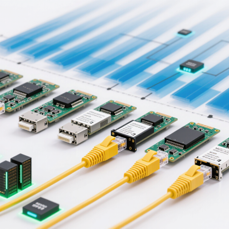
Before choosing an optical SFP module, define what the link must carry and how far it must reach. Record the switch port type, required data rate, and whether the connection uses single-mode or multimode fiber. Check the connector and wavelength at both ends; matching only the fiber type is not enough. Small details matter.
Measure the cable route, including patch panels and service loops, rather than relying only on a floor plan. Compare that distance with the module’s specified reach, leaving margin for connectors and future changes. Know the environment, too. A warm equipment closet can affect whether a module stays within its operating temperature range. Confirm host compatibility and power requirements using equipment documentation and the module datasheet.
Traffic patterns shape the choice. A short server link may need a different rate and optical budget from a campus connection across several buildings. Document the required speed, expected upgrades, link budget, and monitoring needs before ordering. Do not select by reach alone. Check the receiver’s optical-power range as well. Requirements can be uncertain, especially in older buildings; record assumptions and test a representative link before expanding deployment.
Before choosing an optical SFP module, confirm that the switch supports its form factor and data rate. An SFP-shaped module does not automatically work in every SFP port. Check the switch’s documentation for supported module types, port speed, and any firmware requirements. A 1G port may not accept a 10G module, even when the module fits physically. Small detail, big impact.
Match the optical standard to the link. For example, confirm the required wavelength, fiber type, connector, and transmission distance at both ends. A short-reach multimode module and a long-reach single-mode module serve different links. Check that each endpoint uses compatible optics; matching only the connector is not enough. Also review whether the switch supports digital optical monitoring if that feature matters for maintenance. It is easy to focus on the module and overlook the far-end device. That assumption can cause avoidable link problems.
Tips: Read the switch’s supported-transceiver list, then compare it with the module datasheet. Verify speed, wavelength, fiber, and reach before ordering. If specifications seem unclear, ask the equipment supplier to confirm compatibility in writing. One more check is worthwhile.
Compare the optical Ethernet standard and typical maximum link reach, then confirm that the switch supports the module’s form factor, speed, wavelength, and fiber type.
Illustrative IEEE Ethernet link-reach figures: 1000BASE-SX reaches up to 550 m on OM2 multimode fiber; 1000BASE-LX up to 5 km on single-mode fiber; 10GBASE-SR up to 400 m on OM4 multimode fiber; and 10GBASE-LR up to 10 km on single-mode fiber. Actual reach depends on the fiber specification and link design.
An optical SFP is only a good match when its optics suit the installed fiber. Single-mode fiber carries signals over longer distances, while multimode fiber is typically used for shorter links. Check the module datasheet and the cable jacket or site records before ordering; color alone is not dependable. Small mismatch, big headache.
Wavelength matters at both ends of the link. A module transmitting at 1310 nm should connect to equipment designed to receive that wavelength, with the fiber type and supported distance also matching. For bidirectional links, verify the transmit and receive wavelengths are complementary on opposite ends. I have seen wavelength checks skipped when a replacement looked physically identical. It is an easy mistake.
Connector fit needs more than a quick glance. Confirm the connector style, such as LC or SC, and the polish type specified for the equipment. UPC and APC ends should not be treated as interchangeable; their contact surfaces differ. Inspect for dust, too. A clean connector can still be the wrong type, but a dirty one can make a correct pairing fail. Before installation, compare both module labels, fiber specifications, connector details, and link distance. If any item is unclear, pause and check the device documentation rather than guessing.
How to Choose the Right Optical SFP Module?
Match the module’s data rate to the port and the link’s actual traffic needs. Both ends must support compatible rates and optical standards; a faster module will not make a slower port faster. Check the equipment documentation rather than relying on a product label alone. Small details matter.
Next, compare the specified transmission distance with the real route. A fiber run through a building may include patch panels, connectors, and service loops that add length or loss. Also confirm the fiber type and wavelength match the module. Distance ratings are useful, but they are not a guarantee under every installation condition.
Optical budget helps assess whether the signal can reach the receiver reliably. Subtract the receiver’s sensitivity from the transmitter’s minimum output to estimate the available budget, then account for fiber attenuation, connectors, and splices. Keep some margin for aging, repairs, and measurement uncertainty. A link that barely meets the calculation may work today and become unstable later. The arithmetic is not always tidy, especially when old cabling records are incomplete. Measure the installed path when possible, and compare readings with the module’s specifications before deployment.
| Ethernet Standard | Data Rate | Wavelength | Fiber Type | Typical Maximum Distance | Minimum Optical Budget | Common Use |
|---|---|---|---|---|---|---|
| 1000BASE-SX | 1 Gb/s | 850 nm | Multimode fiber (OM2 or better) | Up to 550 m on OM2 | About 7.5 dB | Short-reach links within buildings and data rooms |
| 1000BASE-LX | 1 Gb/s | 1310 nm | Single-mode fiber; some installations use multimode fiber with a mode-conditioning patch cord | Up to 10 km on single-mode fiber | About 9.5 dB | Campus, building, and metro access links |
| 10GBASE-SR | 10 Gb/s | 850 nm | Multimode fiber (OM3 or OM4) | Up to 300 m on OM3; 400 m on OM4 | About 2.6 dB | Short-reach data-center and server-room connections |
| 10GBASE-LR | 10 Gb/s | 1310 nm | Single-mode fiber | Up to 10 km | About 6.2 dB | Building-to-building and campus links |
| 10GBASE-ER | 10 Gb/s | 1550 nm | Single-mode fiber | Up to 40 km | About 11.1 dB | Long-reach metro and inter-site connections |
Optical budgets are approximate minimum values derived from representative transmit-power and receiver-sensitivity limits; actual specifications can vary by module. Allow for connector, splice, and fiber losses when checking a link budget. Confirm the required Ethernet standard, fiber type, wavelength, and supported distance before selecting a module.
Choosing an optical SFP module is only part of the job; verify its performance in the target switch. Check the module’s wavelength, fiber type, reach, connector, and transmission rate against the link plan. Then inspect both connector end faces with a fiber inspection scope. A tiny dust speck can disrupt a link. Clean and reinspect before connecting.
After installation, confirm that the switch recognizes the module and reports stable transmit and receive power. Compare readings with the module’s specified limits, not a generic threshold. Check polarity and test the full path with a power meter or traffic generator. Send traffic in both directions and watch for errors, drops, or unexpected link flaps.
Test it live. I still find it easy to trust a link light too quickly; it confirms connectivity, not quality.
The Uptime Institute’s 2024 Annual Outage Analysis reported that 54% of respondents’ most recent significant outages cost more than $100,000. That figure covers outages broadly, not optical links alone, but it shows why verification matters.
Record module identifiers, measured power, test duration, and error counts. Keep the readings as a baseline. If results drift later, that record helps separate a dirty connector from a failing optic or damaged cable.