
Contract Manufacturing for Injection Molded Plastic Products in North America
(800) 824.0607

RFQ / CONTACT
Contract Manufacturing for Injection Molded Plastic Products in North America | (800) 824.0607

How to Choose a Valve Position Monitor in 2026?

Choosing a Valve Position Monitor in 2026 is no longer a simple matter of matching a switch to a valve stem. Plants now demand clearer feedback, faster diagnostics, and stronger resistance to moisture, vibration, and temperature changes. A small device can protect a large process.

Greg McMillan, a respected process-control author and automation specialist, offers a useful warning: “A measurement is only useful when it is trusted.” That principle applies directly to valve position monitoring. A monitor may show open or closed status, yet still fail during wiring faults, mechanical wear, or poor installation. Trust must be earned through reliable sensing, suitable housing, accurate alignment, and practical maintenance access.

This guide examines the details that often decide performance in the field. It considers valve type, actuator movement, environmental exposure, communication needs, and the value of diagnostic feedback. A compact monitor on a clean indoor line has different demands from one installed beside a vibrating outdoor pipeline. Look closely. Small differences matter.

Certification and compatibility also deserve careful review. Standards, hazardous-area requirements, and plant policies vary by location and application. Product claims should be checked against technical documents, test conditions, and real service records. Marketing language alone is not enough.

The best Valve Position Monitor is not always the most advanced model. Sometimes, a simple, well-sealed switch performs better than a complex device that operators cannot configure or maintain. That is an uncomfortable point. Selection decisions should remain practical, evidence-based, and open to revision after field experience.
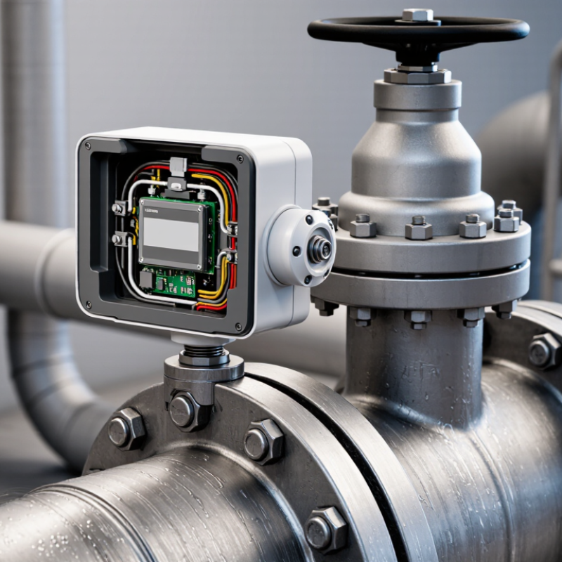
How to Choose a Valve Position Monitor in 2026?

Valve Position Monitors: Definition, Purpose, and Operating Principles

How to Choose a Valve Position Monitor in 2026?

Valve Position Monitors: Definition, Purpose, and Operating Principles

A valve position monitor reports whether an industrial valve is open, closed, or between positions. It is simple. Mounted near the actuator or valve stem, it converts movement into electrical, visual, or network signals.

Operators use these signals to confirm flow-path status, coordinate interlocks, and detect movement that differs from a control command.

During commissioning, I check the monitor while cycling the valve slowly. A bright indicator helps, but the feedback must also match the control system. That matters.

Most monitors use cams and limit switches, magnetic targets, proximity sensors, or rotary position detection. A cam rotates with the stem and triggers set points.

A non-contact sensor detects a target without physical rubbing. This can reduce wear, although installation errors may still create false feedback.

Verify the enclosure rating, temperature range, cable entry, and site suitability. Do not trust a datasheet alone.

Check the valve’s torque, travel, mounting space, and signal type.

When choosing in 2026, begin with process risk rather than fashionable connectivity. Define the required feedback: open and closed status, intermediate position, continuous angle, or diagnostic data.

Match the output to the existing control or safety system. Confirm voltage, current, protocol, and response time.

Visible local indication remains valuable during maintenance. It can expose a reversed cam before startup.

Digital diagnostics help, but they may complicate troubleshooting.

A manual simulation during acceptance testing can reveal loose wiring or poor calibration.

Identify Valve Type, Application Conditions, and Monitoring Requirements

How to Choose a Valve Position Monitor in 2026?

Start by identifying the valve type and its actual movement. A quarter-turn ball or butterfly valve needs different feedback from a rising-stem gate valve. Confirm travel angle, stem rotation, fail position, and mounting space before selecting a monitor. A device that fits the actuator may still report inaccurate positions. That mistake is common.

Application conditions decide the enclosure and sensing method. Record pressure, temperature, vibration, washdown exposure, corrosion risk, and hazardous-area classification. For outdoor equipment, sunlight and condensation can damage weak seals. For steam service, heat transfer can shorten sensor life. The International Energy Agency’s Global Methane Tracker 2024 estimates that fossil fuel operations released nearly 120 million tonnes of methane in 2023. Reliable valve feedback supports faster leak detection and isolation, but position feedback alone cannot prove tight shutoff.

Define the monitoring requirement in operational terms. Is the signal needed for open-close confirmation, intermediate control, emergency shutdown, or predictive maintenance? Select suitable electrical outputs, diagnostic functions, response time, and communication protocols. The ISA-TR84.00.07 technical report emphasizes that safety instrumented functions require documented proof of performance, not casual component selection. That point deserves attention. A simple limit switch may suit a clean utility line, while a networked position transmitter may better support remote assets. Still, more data is not automatically better. The 2024 World Energy Outlook highlights growing digitalization across energy operations, yet poor calibration can turn detailed dashboards into misleading alarms. Field testing, proof-test intervals, and maintenance access should remain part of the specification.

Compare Sensor Technologies, Signal Outputs, and Communication Protocols

Choosing a valve position monitor in 2026 starts with the sensor, not the enclosure. Mechanical switches remain practical for simple open-close feedback. Inductive sensors tolerate vibration and contamination better. Magnetic sensors suit compact assemblies, while Hall-effect devices provide non-contact measurement. For continuous travel, potentiometric or non-contact position sensors offer more detail, but they need careful calibration. My earlier bias favored non-contact sensors; field conditions sometimes prove simplicity more reliable.

Signal output should match the control system. Discrete contacts are inexpensive and easy to troubleshoot. A 4–20 mA signal gives continuous position data and detects some wiring faults. HART adds diagnostics without replacing existing analog wiring. IO-Link can provide device identification, parameter records, and maintenance data through a digital connection. According to the 2024 Industrial Network Market Shares report from HMS Networks, industrial Ethernet represented about 71% of new connected nodes, while fieldbus accounted for roughly 22%. The direction is clear, but conversion gateways still create avoidable complexity.

Protocol selection should reflect distance, cybersecurity rules, maintenance skills, and available infrastructure. Ethernet-based communication supports richer diagnostics, yet it may demand better network design. Fieldbus remains useful where installed assets already work reliably. During commissioning, a monitor showing “open” while the valve is physically closed is not a minor issue. Check mounting alignment, fail-safe behavior, signal scaling, and diagnostic states under real operating conditions. Reports guide the decision; site evidence should decide it. Sources: HMS Networks, Industrial Network Market Shares 2024; IEC 60534-6-2; NAMUR Recommendation NE 107.

How to Choose a Valve Position Monitor in 2026? — Compare Sensor Technologies, Signal Outputs, and Communication Protocols
Sensor Technology Typical Position Capability Primary Signal Output Common Communication Protocols Typical Accuracy or Repeatability Typical Response Time Key Advantages Main Limitations Recommended Applications
Mechanical limit switch Discrete end-of-travel indication; open or closed position Dry contact, SPDT or DPDT; normally open or normally closed Discrete input wiring; commonly integrated into remote I/O or safety circuits Typically within approximately ±1° to ±3°, depending on actuator linkage and adjustment Typically 5–20 ms Robust and economical
Simple commissioning, easy troubleshooting, and broad compatibility with industrial control systems
Mechanical wear, contact bounce, contact oxidation, and limited diagnostics; requires correct mechanical adjustment Quarter-turn valves, basic open/closed feedback, outdoor installations, and applications where low initial cost is important
Inductive proximity sensor Discrete detection of a metal target at one or more preset positions PNP or NPN transistor output; two-wire or three-wire DC versions are common Discrete I/O; IO-Link is available on some sensor designs Typically within approximately ±0.5° to ±2°, depending on target geometry and setup Typically 0.5–5 ms Non-contact sensing
No mechanical contact wear, good switching speed, and reliable operation in dusty environments
Requires a suitable metallic target; sensing distance is limited and performance can be affected by target alignment Fast cycling valves, dusty process areas, compact actuator packages, and installations requiring long sensor life
Magnetic reed switch Discrete end-position detection using a magnet and reed contact Dry contact or solid-state discrete output Discrete input wiring; some versions support IO-Link through an electronic interface Typically within approximately ±1° to ±3° Typically 1–10 ms Low power
Galvanic isolation is possible with dry contacts and the sensor can be installed without a metal target
Reed contacts can be sensitive to shock, vibration, contact bounce, and excessive switching current Compact pneumatic actuators, low-power control cabinets, and applications needing simple isolated contacts
Hall-effect magnetic sensor Discrete or continuous angular position, depending on the sensor and magnetic arrangement Digital switching output, pulse output, PWM, or analog voltage Discrete I/O, PWM input, or vendor-independent analog input; digital interfaces depend on the device Typically approximately ±0.5° to ±2° for continuous position versions Typically below 1 ms to 10 ms No mechanical contact
Long operating life, fast response, and suitability for compact sealed assemblies
Requires a correctly aligned magnetic field; temperature drift and magnetic interference must be considered High-cycle actuators, compact valve assemblies, clean process areas, and applications requiring non-contact feedback
Potentiometric position sensor Continuous angular position, commonly over 90°, 180°, or 360° ranges Analog voltage, commonly 0–5 V or 0–10 V Analog input; may be connected to remote I/O or a controller with signal conditioning Typically approximately ±0.5% to ±2% of full scale Typically 1–20 ms Simple continuous feedback
Provides proportional position information without requiring a field communication network
Wiper wear, sensitivity to electrical noise, limited cable distance, and possible signal loss from open circuits Modulating valves, laboratory or utility systems, and legacy control systems with voltage analog inputs
4–20 mA position transmitter Continuous valve position, typically scaled from 0–100% Two-wire 4–20 mA current loop; 4 mA normally represents 0% and 20 mA represents 100% Analog current input; HART can be superimposed on the 4–20 mA signal when supported Typically approximately ±0.5% to ±1.0% of span Typically 50–250 ms, depending on filtering and update settings Long-distance analog transmission
Strong noise immunity, easy fault detection using live-zero signaling, and wide control-system compatibility
Requires loop power and correct load resistance; provides limited information without a digital overlay Modulating control valves, long cable runs, hazardous-area installations, and process control systems using analog I/O
Digital smart position monitor Continuous position plus configurable open, closed, intermediate, or travel-limit states Discrete outputs, analog output, or a combination of status and diagnostic signals HART, IO-Link, or industrial Ethernet/fieldbus options, depending on the device architecture Typically approximately ±0.25% to ±1.0% of calibrated range Typically 20–250 ms, depending on network and diagnostic settings Diagnostics and configuration
Supports remote setup, travel counters, sensor health data, calibration records, and predictive maintenance functions
Higher cost, more configuration effort, and dependence on compatible host hardware and software Critical process valves, condition monitoring, large plants, and installations requiring asset-management data
Selection note: Choose discrete sensing for simple end-position confirmation, 4–20 mA for dependable long-distance continuous feedback, and a smart digital monitor when diagnostics, remote configuration, or predictive maintenance data are required. Actual accuracy, response time, temperature range, ingress protection, hazardous-area approval, and protocol availability must be verified in the device datasheet.

Evaluate Environmental Ratings, Safety Features, Accuracy, and Durability

How to Choose a Valve Position Monitor in 2026?

Choosing a valve position monitor starts with the environment around the valve. Check the enclosure rating for dust, water jets, condensation, and temporary flooding. A monitor installed beside a washdown line needs stronger protection than one inside a dry control room. Temperature range also matters, especially near steam pipes or outdoor equipment. In field inspections, neglected cable glands often caused more trouble than the monitor itself. That detail is easy to miss.

Safety features deserve practical attention. Look for clear open and closed indication, secure switching, and reliable feedback during partial movement. Hazardous-area installations require suitable protection and correctly matched electrical parameters. Ask for test evidence, not only attractive specifications. Accuracy should match the control system’s needs. Excessive precision may add cost without improving process control. Still, poor calibration can create false confidence. I have seen a valve report “closed” while debris prevented complete seating. That was an installation problem, not simply a sensor failure.

Tips: Compare the stated accuracy with real operating conditions. Test the monitor after wiring, adjustment, vibration, and temperature changes. Select corrosion-resistant materials where chemicals or salty air are present. Check whether the mechanism remains accessible for maintenance. Keep records of calibration dates and observed drift. Do not assume a higher price guarantees longer service life; mounting quality and inspection habits often decide durability.

How to Choose a Valve Position Monitor in 2026?

Practical engineering screening benchmarks for environmental protection, functional safety, position accuracy, and service life.

Use these thresholds as an initial comparison tool. IP ratings are defined by IEC 60529, while safety integrity, accuracy, and cycle-life requirements must be confirmed against the valve assembly, control system, operating environment, and applicable project standards.

Select, Install, and Maintain the Right Valve Position Monitor in 2026

How to Choose a Valve Position Monitor in 2026?

Selecting a valve position monitor starts with the valve’s actual duty, not a product catalogue. The 2024 Grand View Research report valued the global industrial valves market at about USD 78.3 billion in 2023, with continued growth through 2030. More plants now need reliable feedback for automated isolation and process control. Choose a monitor that supports the valve’s travel range, operating temperature, vibration level, and required communication protocol. A rotary valve in a dusty area needs different protection from a clean-water actuator. Small errors matter.

Installation Quality

Installation quality often decides performance. Confirm the open and closed mechanical stops before calibration. Align the indicator with the real stem position, then test both limits from the control room. Check enclosure protection, cable-gland sealing, grounding, and hazardous-area certification where applicable. The 2024 MarketsandMarkets valve positioners report projects market growth from approximately USD 1.5 billion in 2024 to USD 2.0 billion by 2029. That expansion suggests more digital diagnostics, but digital feedback cannot correct poor alignment. Fit it carefully.

Maintenance and Monitoring

Maintenance should create evidence, not assumptions. Record baseline travel time, switch points, signal stability, and actuator stroke after commissioning. Inspect covers for condensation, loose fasteners, corrosion, and damaged seals during planned shutdowns. Compare new readings with the baseline and investigate gradual drift. A quarterly visual check may suit a clean utility service, while severe vibration requires shorter intervals. I would not copy one schedule across every valve. Process criticality, failure history, and environmental exposure should shape it. Recheck the difficult valves first.