Contract Manufacturing for Injection Molded Plastic Products in North America
(800) 824.0607
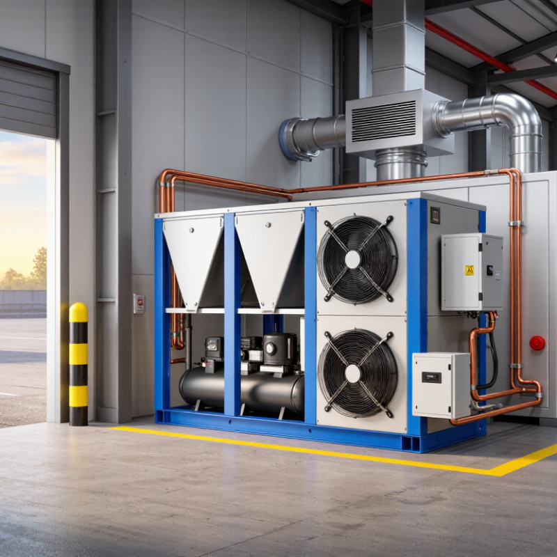
Choosing the right Refrigeration Condensing Unit begins with more than comparing price, horsepower, or brand recognition. It requires a clear view of cooling load, refrigerant type, ambient temperature, operating hours, and service conditions. A unit beside a hot loading dock faces different demands from one inside a cool warehouse.
The International Energy Agency reported in The Future of Cooling that space-cooling electricity demand could more than triple by 2050 without stronger efficiency measures. The UNEP Cooling Emissions and Policy Synthesis Report also warns that cooling-related emissions may more than double by 2050. These figures make equipment selection an operational decision, not a purchasing detail.
Didier Coulomb, former Director General of the International Institute of Refrigeration, stated, “Refrigeration is essential for life.” His observation gives this topic practical weight. A poorly matched condensing unit can raise energy use, shorten compressor life, and create unstable cabinet temperatures. Small errors matter.
This guide examines capacity selection, refrigerant compatibility, compressor technology, condenser performance, controls, noise, maintenance access, and lifecycle cost. It also considers real installation details, such as a 35°C outdoor temperature, restricted airflow, and long refrigerant piping. Manufacturer data must be checked carefully. Nominal capacity alone can mislead.
There is no perfect unit for every site. A lower purchase price may hide higher electricity costs. A premium model may still perform poorly when installed badly. That uncomfortable point deserves attention. By combining manufacturer specifications with field experience, recognized standards, and independent industry data, buyers can make a more defensible choice. The goal is simple: stable cooling, reasonable energy use, and reliable operation over many seasons.
Choosing the right refrigeration condensing unit starts with the peak cooling load, not the average daily load.
Measure product temperature, room dimensions, wall insulation, door openings, lighting, and occupancy. Include infiltration from warm, humid air and heat released by evaporators, fans, and defrost cycles. A practical target is 100–120% of the calculated design duty. This margin supports pull-down periods and unexpected operating changes without creating excessive capacity.
Field experience matters. Record the warmest outdoor condition and the highest product arrival temperature. A small storage room can still face a heavy load after several door openings. I have seen tidy spreadsheets miss pallet staging time and compressor heat. That estimate was not perfect.
Oversizing also deserves caution. An oversized unit may cycle too frequently, reduce humidity control, and increase mechanical stress. A qualified refrigeration professional should review the calculation, refrigerant conditions, ambient temperature, and local installation requirements before final selection.
Tips: Use real operating records when available. Check the worst hour, not the daily average. Add a clear allowance for product pull-down. Keep the final capacity near 100–120% of design duty. Recheck airflow, condenser cleanliness, and door seals during commissioning. Small details matter.
How to Choose the Right Refrigeration Condensing Unit?
Match Operating Temperatures: Set Evaporating and Condensing Design Points
A condensing unit should match real operating temperatures, not only the room setpoint. The evaporating temperature controls product temperature, coil performance, and compressor workload. Frozen storage may need an evaporating design point near -30°C. Chilled food often operates closer to -10°C. These are starting points, not universal rules. Product load, door openings, humidity, and defrost cycles can change the selection.
The condensing design point must reflect the hottest expected heat-rejection condition. Air-cooled systems may face high summer ambient temperatures, dusty coils, or restricted airflow. A small temperature mismatch can increase energy use and reduce capacity. The International Energy Agency reported that cooling consumed about 10% of global electricity in 2018. Better temperature matching has practical value. ASHRAE Handbook—Refrigeration recommends evaluating evaporating and condensing conditions with the actual application and heat-rejection method.
For example, a cooler designed for a 35°C ambient may struggle during a 42°C afternoon. The compressor may run continuously. That is a warning sign. Field measurements often reveal imperfect assumptions: actual suction temperature may differ from the design sheet. Record suction pressure, liquid temperature, discharge pressure, and outdoor temperature before final approval. A conservative design is useful, but excessive temperature lift can waste energy and inflate equipment cost. Recheck the numbers.
Match the condensing unit to the required evaporating and condensing design points. The chart shows representative operating temperatures for common refrigeration applications.
Evaporating temperature is selected according to the required refrigerated space or product temperature. Condensing temperature depends on the ambient or cooling-medium temperature and the required condenser temperature difference. Select a unit whose operating envelope covers both design points, while allowing adequate capacity and stable operation under actual site conditions.
Compare efficiency using COP: cooling capacity divided by compressor power.
For example, a unit delivering 10 kW of cooling with 2.5 kW compressor input has a COP of 4.0. That number looks strong. However, it may exclude condenser fans, controls, and crankcase heaters. Including 0.3 kW of additional power lowers the system COP to 3.57.
Test conditions matter greatly. A condensing unit rated at 35°C ambient temperature may perform very differently at 45°C. Check the evaporating temperature, condensing temperature, refrigerant, and return-gas condition. Then compare units under identical conditions. The International Institute of Refrigeration reports that refrigeration consumes about 17% of global electricity. Small efficiency gains can therefore affect operating costs significantly.
Seasonal performance deserves attention too. The International Energy Agency projects global space-cooling electricity demand could more than triple by 2050 without efficiency improvements. Refrigeration is not identical to space cooling, but the pressure on efficient equipment is comparable.
A higher rated COP is useful, yet it is not the whole answer. Field measurements can disagree with catalog figures. I have seen calculations overlook fan power and defrost cycles. Recheck the assumptions before choosing the unit.
How to Choose the Right Refrigeration Condensing Unit?
Refrigerant selection should begin with GWP100, not end there. The IPCC Fourth Assessment Report lists R744 at GWP100 1, R290 at 3, and R404A at 3,922. These figures show a dramatic climate difference. A one-kilogram R404A leak represents 3,922 kilograms of CO2 equivalent. That number deserves attention.
R744 suits systems requiring high pressure capability and precise controls. R290 offers very low GWP and strong thermodynamic performance, but its A3 flammability classification demands careful charge management and qualified installation. R404A remains familiar in older equipment, yet its high GWP makes leakage costly environmentally. Familiar does not mean future-proof.
The condensing unit must match cooling load, evaporation temperature, ambient conditions, and compressor envelope. Check discharge temperature, oil return, receiver size, and control compatibility. The UNEP 2022 Refrigeration, Air-Conditioning and Heat Pumps Technical Options Committee report supports lower-impact refrigerant transitions, but practical design still matters. A low GWP alone cannot guarantee efficiency. Nor does a high-efficiency compressor excuse poor maintenance.
Field experience often reveals the missed detail: a dusty condenser can raise head pressure, while incorrect superheat can damage the compressor. Measure operating conditions during the hottest expected period. Then compare energy use, safety controls, service skills, and leakage risk. The “best” unit may not be the one with the lowest GWP. It is the one that performs reliably under real operating conditions.
How to Choose the Right Refrigeration Condensing Unit?
A suitable condensing unit must match the refrigerant, operating temperature, and installation environment. Safety verification begins with ASHRAE 34, which classifies refrigerants by toxicity and flammability. Check the refrigerant’s safety group before comparing capacity or efficiency. A higher efficiency rating does not remove safety duties.
EN 378 adds practical requirements for the complete refrigeration system. Review allowable charge limits, machinery-room ventilation, leak detection, pressure protection, and emergency access. The selected unit should support these requirements through compatible components and clear technical documentation. Confirm that valves, electrical parts, controls, and relief devices suit the refrigerant and expected pressure. Do not treat the condensing unit as an isolated product.
Look closely at the installation site. Measure room volume, airflow paths, heat sources, and service clearances. A small room can change the risk assessment significantly. During commissioning, record refrigerant charge, pressure readings, detector response, and ventilation performance. Field conditions often expose assumptions missed during design. A neat datasheet is not proof. Ask qualified engineers to review the final configuration against ASHRAE 34 and EN 378. Requirements may depend on occupancy, equipment location, refrigerant class, and national implementation. Keep the assessment current after modifications, even when the replacement unit appears similar.
| Selection Dimension | Verification Item | Reference Data / Requirement | Why It Matters for a Condensing Unit | Recommended Evidence Before Purchase |
|---|---|---|---|---|
| 1. Refrigerant Safety Classification | ||||
| ASHRAE 34 classification | Confirm toxicity and flammability group | A1 Lower toxicity / no flame propagation A2L Lower toxicity / mildly flammable A3 Lower toxicity / highly flammable | The safety group affects allowable charge, machinery-room design, ventilation, electrical equipment, leak detection, service procedures, and installation location. | Current refrigerant classification listing, safety data sheet, equipment nameplate, and design calculation based on the exact refrigerant composition. |
| EN 378 refrigerant category | Check the applicable installation and occupancy conditions | EN 378 evaluates refrigerant hazards together with system location, access category, occupancy, room volume, charge, and application type. | The same refrigerant may require different safeguards depending on whether the system is installed in a public area, workplace, machinery room, or restricted-access space. | Application risk assessment identifying room category, occupancy, refrigerant safety group, charge, and required protective measures. |
| 2. Refrigerant Suitability and Environmental Data | ||||
| Common refrigerant option | ASHRAE 34 safety group and approximate GWP1 | R134a: A1, GWP 1,430 R410A: A1, GWP 2,088 R32: A2L, GWP 675 R290: A3, GWP about 3 R744 (CO2): A1, GWP 1 | Refrigerant choice influences operating pressure, compressor discharge temperature, oil compatibility, heat-exchanger sizing, controls, service qualifications, and regulatory obligations. | Verify the refrigerant is approved for the intended condensing unit, operating envelope, pipework, valves, compressor lubricant, and local environmental legislation. |
| Operating pressure | Compare design pressure with system pressure | R744 systems operate at substantially higher pressures than many HFC and hydrocarbon systems. The exact design and relief pressures must be taken from the equipment documentation. | Insufficient pressure rating can cause rupture, relief-device discharge, premature component failure, or non-compliance with pressure-equipment rules. | Pressure-temperature chart, maximum allowable pressure, relief-device specification, and certificates for vessels, piping, heat exchangers, and service valves. |
| 3. Charge and Room Safety | ||||
| Refrigerant charge | Calculate the actual charge in the complete circuit | Use the total system charge, not only the factory charge in the condensing unit. For flammable refrigerants, charge limits depend on refrigerant properties, room size, application category, and protective measures. | Incorrect charge assessment can invalidate the safety design, especially for A2L and A3 refrigerants installed in occupied spaces. | System charge calculation including pipe length, receiver volume, evaporator, condenser, liquid-line volume, and commissioning allowance. |
| Room volume and occupancy | Identify the smallest connected occupied space | EN 378 charge-limit calculations use the relevant room volume and installation category. A smaller room generally produces a more restrictive allowable charge. | A unit acceptable in a plant room may not be acceptable in a retail area, food room, office, or other occupied location without additional controls. | Scaled floor plan, room volume calculation, occupancy classification, access restrictions, and documentation of connected rooms or air paths. |
| Leak detection | Determine whether detection is required | Detection and alarm provisions depend on refrigerant type, charge, room use, system location, and the applicable EN 378 installation requirements. | Detection can initiate alarm, ventilation, equipment isolation, or controlled shutdown before refrigerant concentration reaches a hazardous level. | Detector location plan, calibrated sensor range, alarm set points, response time, maintenance schedule, and control-system cause-and-effect matrix. |
| Ventilation | Provide natural or mechanical ventilation where required | Ventilation design must account for refrigerant density, likely leak location, room geometry, airflow path, discharge location, and required emergency operation. | R290 is heavier than air and may accumulate near the floor. Other refrigerants require assessment based on their physical properties and the applicable standard. | Ventilation airflow calculation, intake and exhaust locations, fan suitability, emergency power requirements, and commissioning test records. |
| 4. Condensing Unit Technical Compatibility | ||||
| Cooling capacity | Match capacity at the actual design point | Compare capacity at the specified evaporating temperature, condensing temperature, suction superheat, liquid subcooling, and ambient temperature. | Nominal capacity published at another rating condition may lead to inadequate cooling, excessive cycling, or high energy consumption. | Certified performance tables or selection software showing capacity, input power, mass flow, and current at the actual operating conditions. |
| Operating envelope | Check evaporating and condensing temperature limits | Verify minimum and maximum suction pressure, maximum condensing pressure, discharge temperature, motor limits, start conditions, and allowable pressure ratio. | Operation outside the envelope can overheat the compressor, dilute oil, cause liquid return, trip protection, or shorten service life. | Compressor envelope chart, controller settings, high-pressure and low-pressure protection values, and commissioning limits. |
| Oil and materials compatibility | Confirm oil, seals, gaskets, and electrical compatibility | Refrigerants require compatible lubricants and elastomers. Hydrocarbon systems also require equipment specifically designed and assessed for flammable refrigerants. | Incompatible materials can cause leakage, lubrication failure, swelling, embrittlement, or loss of electrical insulation. | Refrigerant-specific component list, lubricant specification, material compatibility statement, and manufacturer’s approved application range. |
| Electrical and ignition control | Assess ignition sources for flammable refrigerants | For A2L and A3 refrigerants, identify potential ignition sources and apply the applicable equipment, wiring, switching, and installation requirements. | Relays, contactors, motors, terminal connections, hot surfaces, and service tools may become ignition sources if not properly assessed. | Electrical risk assessment, component certification or suitability declaration, enclosure information, wiring diagram, and installation instructions. |
| 5. Protection, Installation, and Documentation | ||||
| Pressure protection | Verify high-pressure control and relief protection | Provide protection against excessive pressure using correctly selected controls, pressure-limiting devices, relief valves, and safe discharge arrangements where required. | Blocked airflow, non-condensable gases, fire exposure, or overcharging can create dangerous pressure conditions. | Pressure-device set points, relief-valve sizing calculation, discharge routing, test certificates, and periodic inspection procedure. |
| Isolation and service access | Provide safe isolation and accessible service points | Design for refrigerant recovery, isolation, pressure measurement, component replacement, and prevention of accidental release. | Proper isolation reduces exposure during maintenance and helps technicians work without opening the entire circuit unnecessarily. | Valve schedule, lockout/tagout procedure, service-port layout, recovery connection details, and maintenance instructions. |
| Leak-tightness and commissioning | Test the completed installation | Perform strength testing, leak testing, evacuation, charging, functional testing, and safety-control verification according to the applicable standard and manufacturer instructions. | Factory-tested equipment can still leak because of field joints, vibration, transport damage, incorrect brazing, or installation errors. | Pressure-test record, leak-test record, vacuum record, refrigerant charge record, detector test, ventilation test, and commissioning checklist. |
| Documentation and marking | Confirm traceable compliance information | Equipment should identify the refrigerant, charge, design pressures, warnings, operating limits, and required installation or service precautions. | Clear marking prevents incorrect charging, unsafe service methods, and use of incompatible replacement parts. | Nameplate, user manual, installation manual, wiring diagram, declaration of conformity where applicable, risk assessment, and service log. |
| 6. Practical Selection Decision | ||||
| Preferred selection outcome | Approve the condensing unit only when all critical checks pass | Capacity matched Pressure rated Charge compliant Safety controls verified | A unit should be selected as a complete safety-engineered system rather than by cooling capacity alone. | Signed design review confirming ASHRAE 34 classification, EN 378 assessment, charge limit, room conditions, equipment compatibility, protection devices, and commissioning requirements. |