
How to Fit Quick Connect Fittings?
Installing a Quick Connect Fitting looks simple, yet small mistakes can cause leaks, pressure loss, or sudden disconnection. This guide explains how to fit quick connect fittings safely, clearly, and with repeatable results. It focuses on hose preparation, fitting compatibility, sealing surfaces, insertion depth, and final inspection. These details matter in pneumatic lines, water systems, fuel equipment, and industrial machinery.
Fluid-connectivity specialist Mark J. Schneider says, “A quick connection is reliable only when the tube, seal, and locking mechanism work together.” That practical warning deserves attention. The fitting body may look strong, but a scratched tube can damage the internal seal. A dirty socket can prevent full engagement. Even a slight angle may leave the connection unstable.
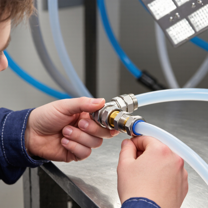
Before Fitting Quick Connect components, confirm the fitting size, thread standard, pressure rating, and working temperature. Do not judge compatibility by appearance alone. Cut tubing squarely with a sharp tool. Remove burrs without thinning the tube wall. Push the tube firmly until it reaches the internal stop. Then pull it gently to verify engagement.
Listen for the click.
A careful installer also checks the manufacturer’s instructions and tests the assembled line at a controlled pressure. Never tighten a push-fit connection to compensate for incorrect tubing. That approach may hide the problem briefly. It can also damage the fitting.
This guide includes practical checks, but it cannot replace site-specific engineering judgment. Some applications require additional clamps, thread sealant, or professional inspection. Mistakes happen, especially in cramped spaces. The important step is recognizing them before the system operates under load.
Understanding Quick Connect Fitting Types and Applications
How to Fit Quick Connect Fittings
Understanding Quick Connect Fitting Types and Applications
Quick connect fittings join hoses, tubes, and equipment without lengthy threading work. Their design supports faster assembly and easier maintenance. Common types include push-to-connect, cam-lock, barbed, and threaded fittings. Push-to-connect models suit clean pneumatic lines and low-pressure tubing. Barbed fittings grip flexible hoses with internal ridges. Cam-lock fittings work well for temporary fluid transfer. Threaded versions provide a firmer connection for fixed installations.
Application matters more than convenience. Check the medium, pressure, temperature, tube material, and connection size before fitting anything. Air systems may tolerate different seals than water or chemical lines. Some fittings resist vibration better than others. A poor match can cause leakage, hose movement, or premature seal damage. Measure carefully. Guessing is expensive.
Turn off pressure and drain trapped fluid before installation. Cut tubing squarely, then remove dust and sharp edges. Push the tube fully into the fitting until it stops. Give it a gentle pull. It should remain secure. For threaded connections, tighten firmly without forcing the body. Excessive torque can crack plastic components or distort seals. Inspect the O-ring for cuts, flattening, or dirt. This small step is often missed. Test the assembled line slowly and watch for bubbles, movement, or pressure loss. Recheck the connection after the system reaches normal operating temperature. The fitting may look perfect, but real conditions can reveal a weak installation.
How to Fit Quick Connect Fittings? - Understanding Quick Connect Fitting Types and Applications
| Fitting Type | Connection Method | Typical Compatible Media | Typical Pressure Range | Typical Temperature Range | Common Applications | Basic Fitting Procedure |
|---|---|---|---|---|---|---|
| Push-to-Connect Tube Fitting Fast installation | A tube is pushed through an internal collet and sealed with an O-ring. | Compressed air, vacuum, inert gases, water, and selected low-pressure fluids, depending on the seal and body material. | Commonly up to approximately 10 bar for pneumatic service; the actual rating depends on tube size, material, and temperature. | Often about −20°C to 80°C with standard polymer seals; higher or lower limits require suitable materials. | Pneumatic controls, automation equipment, instrumentation, air preparation units, and compact tubing assemblies. | Cut the tube squarely, remove burrs, insert it fully to the tube stop, and pull lightly to confirm retention. Depress the release collar before removing the tube. |
| Barbed Quick-Connect Fitting Flexible tubing | A tapered barb grips the inside of flexible tubing; a clamp may be added for demanding service. | Water, air, fuel, chemicals, and other fluids only when the tubing and fitting materials are chemically compatible. | Frequently used in low- to medium-pressure systems; the safe rating is strongly affected by tubing hardness and clamp selection. | Commonly about −40°C to 80°C for general-purpose elastomer tubing; verify the rating for the selected hose. | Irrigation, laboratory equipment, drainage, low-pressure fluid transfer, and small pump systems. | Cut the hose cleanly, push it completely over the barb, and secure it with an appropriate clamp when required. Do not use a hose that is too loose or damaged. |
| Cam-and-Groove Coupling Hose transfer | Two arms lock the male adapter into the female coupler; no wrench is normally required. | Water, wastewater, agricultural liquids, dry bulk materials, oils, and selected chemicals with compatible seals. | Commonly used from vacuum service to approximately 10 bar, depending on size, material, and coupling design. | Often about −25°C to 80°C with common elastomer seals; temperature limits vary by seal compound. | Tank transfer, agricultural irrigation, chemical handling, dewatering, and large-diameter hose connections. | Inspect the gasket, align the adapter and coupler, insert the adapter fully, and close both cam arms evenly. Never pressurize an incompletely locked coupling. |
| Pneumatic Quick Coupler Compressed air | A plug enters a socket and locks with a sleeve, ball-lock mechanism, or equivalent retainer. | Compressed air and inert gases such as nitrogen, when the coupling is rated for the gas. | Commonly approximately 7–15 bar in industrial pneumatic systems; confirm the pressure rating stamped or specified for the coupling. | Often about −20°C to 80°C for standard pneumatic service. | Air tools, production lines, pneumatic cylinders, maintenance drops, and test equipment. | Shut off and bleed pressure, inspect the plug and seal, insert the plug until locked, and test for leakage before operation. Use a safety lock or whip-check where required. |
| Hydraulic Quick Coupler High pressure | A locking sleeve, ball-lock, or screw-to-connect mechanism joins the hydraulic plug and socket. | Hydraulic oil and other approved hydraulic fluids; compatibility must include the hose, seals, and system fluid. | Commonly approximately 100–350 bar for industrial and mobile equipment; specialized couplers can be rated higher. | Often about −20°C to 100°C, subject to seal material, fluid type, and manufacturer limits. | Agricultural machinery, construction equipment, hydraulic power units, lifting equipment, and mobile attachments. | Stop the system, fully relieve trapped pressure, clean both halves, align without forcing, and lock completely. Never connect or disconnect a pressurized hydraulic line. |
| Flat-Face Hydraulic Coupler Low contamination | Flat mating faces seal when the coupler is locked, minimizing fluid loss and air inclusion during connection. | Hydraulic oil and selected biodegradable or fire-resistant hydraulic fluids when approved by the seal and body materials. | Commonly approximately 200–400 bar, depending on size and coupling construction. | Often about −25°C to 100°C, with the seal compound determining the final limit. | Excavators, loaders, hydraulic attachments, road equipment, and systems exposed to dirt or frequent connection cycles. | Clean both flat faces, release all line pressure, align the halves axially, engage the locking sleeve, and verify that the sleeve is fully seated. |
| Dry-Break Coupling Minimal spillage | Valved halves open only after they are correctly connected, reducing leakage and vapor release. | Fuels, solvents, chemicals, pharmaceutical fluids, and other liquids requiring controlled disconnection. | Commonly approximately 5–30 bar, depending on the coupling size, valve design, and fluid service. | Often about −20°C to 120°C, subject to body, seal, and chemical compatibility. | Chemical transfer, process skids, fuel handling, laboratory systems, and controlled fluid distribution. | Confirm the line is isolated, clean the mating surfaces, align the coupling, engage the locking mechanism fully, and check for leaks before opening the system. |
| Refrigeration Quick Coupler Service access | A self-sealing coupling connects service hoses to refrigeration or air-conditioning circuits. | Refrigerants and refrigeration oils only when the coupling, hose, and seals are rated for the specific refrigerant. | Often approximately 30–45 bar for many service applications; systems using higher-pressure refrigerants require higher-rated equipment. | Commonly about −40°C to 125°C, depending on refrigerant, seal material, and service equipment. | HVAC maintenance, refrigeration charging, recovery, evacuation, and pressure testing. | Verify refrigerant compatibility, isolate or control the circuit as required, connect the coupler straight onto the service port, and confirm that the valve opens only after secure engagement. |
| Instrumentation Quick Connect Small-bore tubing | A precision plug-and-socket connection uses an O-ring, metal seal, or face seal for repeatable service access. | Air, gases, water, hydraulic fluids, and process liquids compatible with the selected materials. | Commonly approximately 10–250 bar, depending on tube size, connection design, and sealing method. | Often about −40°C to 150°C, depending on metal, polymer, and seal selection. | Pressure gauges, calibration equipment, analytical instruments, sampling panels, and test manifolds. | Depressurize the line, keep the connection clean, align the plug with the socket, lock it without side loading, and perform a pressure or leak test. |
Important fitting guidance: Always confirm thread form, tube or hose size, pressure rating, temperature rating, sealing material, and fluid compatibility before installation. Pressure and temperature values shown are typical application ranges rather than universal ratings; the lowest-rated component in the complete assembly determines the safe operating limit.