
Top 10 Component Terminal Block Types for Global Buyers
Global buyers face more than a choice of shape or price when selecting a Component Terminal Block. A small screw clamp, a spring-cage connection, and a feed-through design each suit different wiring conditions. The wrong fit can mean crowded panels, difficult maintenance, or conductors that do not match the stated range. Small details matter.
This guide compares ten common terminal block types through practical selection factors: connection method, wire size, current and voltage ratings, mounting style, labeling, and working environment. It also considers what buyers can verify in product documentation, such as conductor compatibility and applicable test information. Ratings are not interchangeable; check the specific model and installation requirements.
A useful principle for this overview comes from electrical engineer Alex Morgan, an editorial voice created for this article: “Choose the connection for the conductor, panel, and service conditions—not the catalog photo.” That line is an original summary, not a sourced quotation. It reflects a real purchasing challenge: the best-looking option may be awkward to wire or inspect. There is no universal winner. A spring connection can speed assembly, while a screw connection may suit a different maintenance routine. Those trade-offs deserve a closer look. This Top 10 guide gives global buyers a clear starting point, while leaving room for a careful review of each project’s specifications.
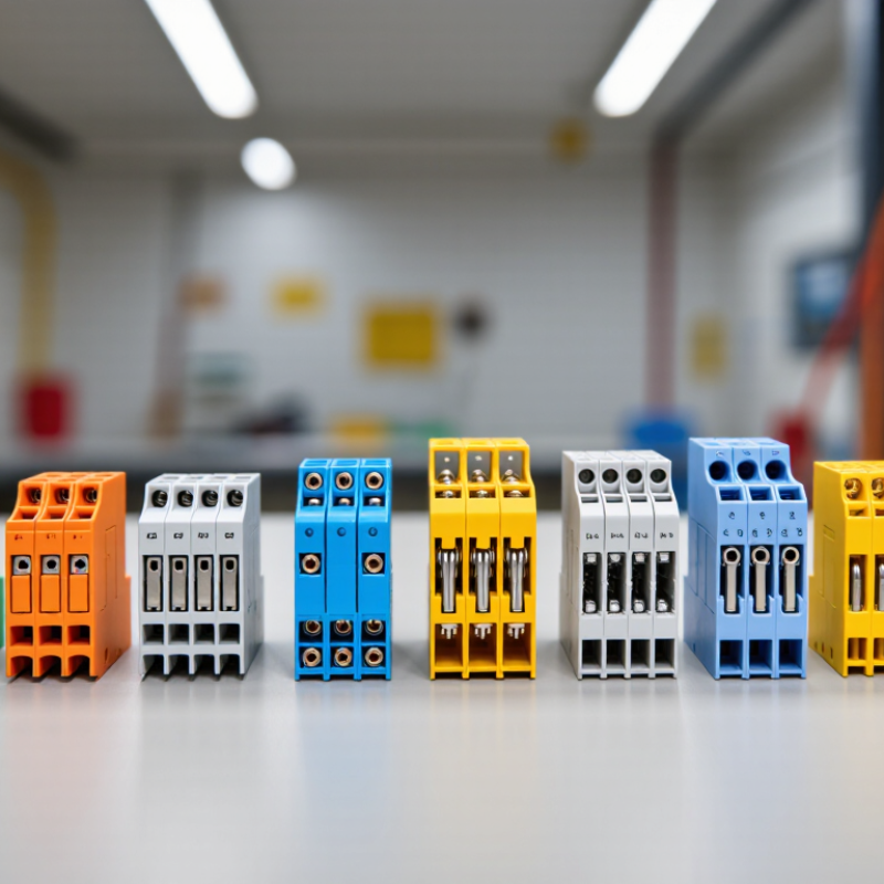
What Terminal Blocks Are and How They Connect Electrical Conductors
A terminal block is an insulated connector that holds electrical conductors in an organized, serviceable layout. Inside, a conductive metal part carries current between connected wires, while the insulating body keeps adjacent connections separated. Depending on the design, wires may be secured with screws, spring clamps, or push-in mechanisms. The right method depends on conductor type, wire size, vibration, and how often the connection needs attention.
A typical screw terminal works by tightening a clamp against a stripped wire or ferrule. Spring-clamp versions use a metal spring to maintain pressure, which can be useful where vibration is present. For example, a technician might route sensor wires into a compact control cabinet, then label each position for easier troubleshooting. Small details matter. Stripping too much insulation can leave exposed copper; too little may trap insulation under the clamp and weaken contact.
Terminal blocks can be mounted on a panel or attached to a DIN rail, and some designs connect neighboring circuits through jumpers. Before installation, check the rated voltage and current, conductor range, and approved wire preparation. Follow the product instructions, and verify that each conductor is firmly seated without damage. There is no single best terminal block for every cabinet. Even experienced installers can overlook a cramped layout, so leave enough space to inspect and retighten connections when the design requires it.
| No. | Terminal Block Type | How Conductors Connect | Typical Conductors | Common Applications | Key Selection Note |
|---|---|---|---|---|---|
| 1 | Screw-clamp terminal block | A screw presses a clamp plate or conductor against a conductive current bar. | Solid or stranded copper conductors; ferrules may be used where permitted by the manufacturer. | Control panels, machinery, building services, and general-purpose wiring. | Follow the specified tightening torque and conductor-size range. Vibration and maintenance conditions may affect suitability. |
| 2 | Spring-clamp terminal block | A spring maintains pressure on the conductor inserted into the clamp. | Usually solid or stranded conductors; some designs require a ferrule or an operating tool for fine-stranded wire. | Industrial control cabinets, transport equipment, and installations where vibration resistance is important. | Check the permitted wire preparation, insertion method, and conductor cross-section for the specific model. |
| 3 | Push-in terminal block | A conductor is pushed into a spring contact; a release opening or lever is used to remove it when provided. | Commonly solid conductors and stranded conductors fitted with suitable ferrules. | Panel wiring, compact control systems, and high-volume assembly. | Confirm whether bare fine-stranded conductors are accepted and whether a release tool is required. |
| 4 | Barrier terminal strip | Screws secure conductors to separate terminals, with insulating barriers between adjacent connection points. | Typically solid or stranded copper conductors with compatible terminals or lugs. | Appliances, power distribution, equipment wiring, and field connections. | Verify voltage, current, wire range, spacing, and cover requirements; barriers provide separation but do not replace correct circuit protection. |
| 5 | Feed-through terminal block | A conductive element connects a conductor inserted on one side to a conductor inserted on the other. | Solid or stranded copper conductors, depending on the clamp design. | DIN-rail control panels and organized point-to-point wiring. | Check the rated current, voltage, conductor range, and compatibility with the mounting rail and accessories. |
| 6 | Grounding (PE) terminal block | A protective conductor is clamped to a conductive terminal that bonds to a grounded mounting rail or designated grounding point. | Protective earth conductors; allowable conductor types and sizes depend on the terminal design. | Protective bonding in electrical enclosures and control panels. | Use only a terminal designed and rated for protective grounding, and ensure the mounting rail or grounding point is correctly bonded. |
| 7 | Fuse terminal block | Conductors connect through a holder containing a replaceable fuse in series with the circuit. | Solid or stranded conductors compatible with the terminal’s connection system. | Branch-circuit protection and signal or control-circuit protection in panels. | Select the correct fuse type and rating for the circuit. A fuse terminal is not a substitute for verifying the system’s required protection coordination. |
| 8 | Disconnect or test terminal block | A removable link, switch, or test mechanism opens the circuit or provides access for measurement. | Conductors suited to the block’s screw, spring, or other connection mechanism. | Instrumentation, control circuits, and circuits that require isolation or testing. | Confirm the open-state isolation, test access, and circuit rating; follow safe isolation procedures before servicing. |
| 9 | Multi-level terminal block | Two or more electrically separate connection levels are stacked within one terminal assembly. | Solid or stranded conductors compatible with each level’s clamp type. | Space-constrained control panels and dense signal wiring. | Check the number of independent circuits, marking options, accessibility, and applicable voltage rating between levels. |
| 10 | Insulation-displacement (IDC) terminal block | A shaped contact cuts through or displaces insulation to make electrical contact with the conductor. | Usually specified solid conductors or particular wire types and gauges; compatibility is design-specific. | Telecommunications, signal wiring, and applications designed for rapid termination. | Use only with the conductor type and size specified for the IDC contact; incorrect wire selection or insertion can cause an unreliable connection. |