
Contract Manufacturing for Injection Molded Plastic Products in North America
(800) 824.0607
Choosing a reliable Rf Coaxial Connector manufacturer is rarely a simple price comparison. Global buyers must examine signal performance, manufacturing consistency, documentation, and practical support. A connector may look excellent under showroom lighting. Its real character appears after repeated mating, vibration, temperature changes, and installation beside crowded cable assemblies.
David M. Pozar, author of Microwave Engineering, explains, “A transmission line is a two-conductor structure that supports the propagation of electromagnetic waves.” That principle matters when selecting RF connectors. Geometry controls impedance. Surface quality affects loss. Poor alignment can create reflections that quietly damage system performance. In a laboratory, this may appear as an unexpected ripple on a network analyzer. In the field, it may become a weak satellite link or unstable test result.
This guide reviews leading Rf Coaxial Connector manufacturers for international buyers. It considers connector families, frequency ranges, materials, plating, return loss, insertion loss, interface compatibility, and production quality. It also examines whether suppliers provide drawings, test reports, samples, and responsive engineering assistance. These details often separate a dependable source from a polished catalog.
No ranking is perfect. Application requirements differ. A manufacturer suited to 5G infrastructure may not fit aerospace testing or compact instrumentation. Buyers should verify current certifications, lead times, minimum order quantities, and regional support before committing. Experience teaches an uncomfortable lesson: the cheapest connector can become the most expensive component after rework, downtime, and repeated testing. The strongest choice balances measurable RF performance with dependable communication and traceable quality.
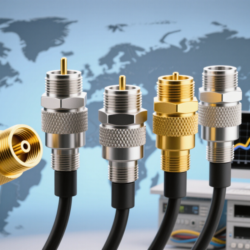
RF coaxial connectors join coaxial cables to antennas, radios, filters, and test equipment. Their structure is simple but precise: a center contact carries the signal, while an insulating dielectric maintains spacing. A conductive outer shell provides shielding and the return path. The interface ends with a threaded, snap-on, or push-pull coupling system.
According to MarketsandMarkets’ RF cable market report, demand is driven by wireless infrastructure, aerospace systems, and growing test equipment needs. Grand View Research also identifies telecommunications and automotive electronics as important application areas. In practice, connector performance depends on more than frequency rating. Impedance, insertion loss, return loss, shielding effectiveness, and mechanical durability all matter. A connector may look robust but still fail after repeated vibration or poor cable preparation. That detail is often underestimated.
Tips: Match the connector to the cable diameter and impedance before purchasing. Check the datasheet for operating frequency, voltage, temperature, and mating cycles. IEC 61169 guidance can support interface selection, but field conditions still require testing. Measure return loss after assembly when signal integrity is critical. Small errors matter. A slightly damaged contact or loose coupling nut can create unstable readings, especially in high-frequency applications.
Evaluating global RF coaxial connector manufacturers requires more than comparing catalog prices. Start with application experience. Ask whether the manufacturer has handled your frequency range, impedance, power level, and installation environment. A supplier should explain insertion loss, return loss, VSWR, shielding, and mechanical limits in practical terms.
Technical evidence matters. Request drawings, material specifications, tolerance data, and recent inspection records. Check whether connectors undergo mating-cycle, vibration, temperature, salt-spray, and environmental sealing tests. Reliable manufacturers can provide traceability from raw materials to finished batches. Look for calibrated equipment and clear quality procedures. Certifications can support trust, but certificates alone prove little. Verify their scope and validity.
Communication reveals operational maturity. Can the engineering team review your interface, cable type, and mounting constraints? Can production maintain stable dimensions across repeated orders? Ask for samples before approving volume production. Inspect plating thickness, contact alignment, thread quality, and connector fit under realistic conditions. Delivery performance also matters, especially when customs documents and regional compliance requirements differ. A responsive supplier may still make mistakes. That is normal, but unclear corrective actions are a warning sign. I would record every test result, open question, and agreed tolerance before placing a global order. Shamefully, many buyers skip this step when the first sample looks acceptable.
Top RF Coaxial Connector Manufacturers for Global Buyers
Leading RF Coaxial Connector Manufacturers by Product Capability
Product capability matters more than a large catalogue. Grand View Research estimates the global RF connectors market was worth about USD 1.8 billion in 2023, with steady growth expected through 2030. This demand reflects higher-frequency wireless networks, satellite systems, test equipment, and industrial controls. Buyers should compare operating frequency, impedance stability, insertion loss, return loss, and power handling at the same time.
A capable manufacturer should support common interfaces, including SMA, N, TNC, BNC, and 2.92 mm designs. It should also provide straight, right-angle, panel-mount, bulkhead, and cable-assembly options. Precision machining matters. A poorly aligned contact can increase VSWR and weaken signal integrity. Products designed around IEC 61169 and MIL-STD-348 requirements offer a clearer technical baseline, although compliance claims still require verification.
MarketsandMarkets reports continued growth in RF connector demand, driven by 5G infrastructure and aerospace applications. Manufacturers with stronger capabilities usually provide vector-network-analyzer data, mating-cycle testing, temperature testing, and material traceability. Check the details. A polished datasheet is not proof of consistent production. In practical sourcing work, samples can perform well while later batches vary. That risk deserves attention. Ask for lot-based inspection records, dimensional reports, and calibration evidence before approving a global supplier.
| Capability Profile | Primary Product Families | Typical Frequency Capability | Common Impedance | Interface Options | Contact and Plating Options | Typical VSWR Performance | Environmental Capability | Applicable Standards | Typical Applications | Customization Strength | Best Fit for Global Buyers |
|---|---|---|---|---|---|---|---|---|---|---|---|
| Profile 01 General-Purpose RF | Board-to-board, cable, panel, bulkhead and right-angle coaxial connectors | DC to 6 GHz | 50 Ω and 75 Ω | BNC, TNC, SMA, SMB, SMC, MCX and MMCX | Gold-plated center contacts; nickel- or passivated stainless-steel bodies | Typically ≤1.30:1 up to 3 GHz | Operating temperatures commonly from −55°C to +85°C; sealed versions available | IEC 61169 series; RoHS and REACH-compliant material options | Test equipment, industrial controls, wireless devices and instrumentation | High | Buyers seeking broad catalog coverage and cost-efficient standard parts |
| Profile 02 High-Frequency Precision | Precision cable assemblies, end-launch, edge-launch and bulkhead connectors | DC to 18 GHz | 50 Ω | SMA, 3.5 mm, 2.92 mm and precision 2.4 mm interfaces | BeCu or brass contacts with gold plating; stainless-steel precision bodies | Typically ≤1.25:1 up to 18 GHz | Operating temperatures commonly from −55°C to +125°C | IEC 61169-15 and applicable precision RF interface specifications | Vector network analyzers, laboratory equipment, radar and microwave modules | Very High | Buyers prioritizing repeatability, low insertion loss and measurement accuracy |
| Profile 03 Millimeter-Wave | Ultra-high-frequency connectors, launch connectors and precision adapters | DC to 67 GHz | 50 Ω | 1.85 mm, 2.4 mm, 2.92 mm and 2.92 mm-compatible interfaces | Precision gold-plated contacts; stainless-steel or passivated alloy bodies | Typically ≤1.35:1 within the specified operating band | Commonly −55°C to +85°C; controlled-mating designs available | IEC 61169-related requirements and manufacturer-specific millimeter-wave specifications | 5G research, aerospace testing, automotive radar and high-speed test systems | Very High | Engineering teams requiring controlled impedance and tight mechanical tolerances |
| Profile 04 Low-PIM Infrastructure | Outdoor feeder connectors, jumper assemblies, adapters and weatherproof bulkheads | DC to 6 GHz | 50 Ω | 7/16 DIN, 4.3-10, N-type, 4.1/9.5 and other base-station interfaces | Silver- or passivated contacts; low-PIM plating systems and ruggedized bodies | Typically ≤1.20:1 up to 3 GHz | IP67 or higher on sealed versions; commonly −40°C to +85°C | IEC 61169; IEC 60529 ingress protection; RoHS and REACH options | Cellular infrastructure, distributed antenna systems and radio base stations | High | Telecom buyers needing low passive intermodulation and outdoor durability |
| Profile 05 Harsh-Environment | Sealed cable connectors, rugged bulkheads, receptacles and high-vibration assemblies | DC to 18 GHz | 50 Ω | SMA, TNC, N-type, SMP and ruggedized multi-contact RF interfaces | Gold-plated contacts; stainless-steel or corrosion-resistant alloy shells | Typically ≤1.35:1 up to 6 GHz | IP67 to IP68 designs; vibration, shock, salt-mist and temperature-cycle options | IEC 60529; MIL-STD-202 test methods; applicable IEC 61169 requirements | Aerospace, defense electronics, marine systems and outdoor communications | High | Global projects with demanding sealing, vibration and corrosion requirements |
| Profile 06 Miniature and Board-Level | PCB receptacles, board-to-board connectors, cable plugs and micro-coax assemblies | DC to 12 GHz | 50 Ω | MMCX, MCX, U.FL-compatible, MMBX, SMP and SMPM interfaces | Gold-plated contacts; stamped or machined contacts depending on volume | Typically ≤1.40:1 up to 6 GHz | Operating temperatures commonly from −40°C to +85°C | Applicable IEC 61169 requirements; RoHS and REACH material options | IoT gateways, compact radios, medical electronics and portable instruments | Very High | OEMs requiring compact footprints, automated assembly and high-density layouts |
| Profile 07 High-Power RF | High-power cable connectors, pressurized interfaces, feeder adapters and transmission-line components | DC to 3 GHz | 50 Ω | 7/16 DIN, N-type, 7/8-inch feeder and other large-format coaxial interfaces | Silver-plated or high-conductivity contacts; copper-alloy conductors | Typically ≤1.25:1 within the rated frequency range | Outdoor-rated sealing; commonly −40°C to +85°C; high-power thermal designs | IEC 61169; IEC 60529 for sealed products; project-specific safety requirements | Broadcast transmitters, cellular networks, public-safety radio and RF power systems | Medium to High | Infrastructure buyers focused on power handling, thermal stability and service life |
| Profile 08 Automotive and Transportation | FAKRA-type housings, sealed coaxial terminals, cable assemblies and multi-port modules | DC to 9 GHz | 50 Ω | Automotive keyed interfaces, SMA, HFM-compatible and mini-coaxial formats | Gold-plated signal contacts; tin-plated cable terminals; keyed polymer housings | Typically ≤1.50:1 up to 6 GHz | Commonly −40°C to +105°C; vibration, thermal-cycle and moisture resistance | USCAR-2, LV214, IEC 60529 and applicable automotive quality requirements | GNSS, telematics, infotainment, vehicle radar and camera systems | High | Automotive and mobility programs requiring keyed, sealed and vibration-resistant solutions |
| Profile 09 Custom Cable Assemblies | Flexible, semi-rigid and conformable coaxial cable assemblies with overmolding options | DC to 40 GHz | 50 Ω and selected 75 Ω configurations | SMA, N-type, TNC, BNC, 2.92 mm, 2.4 mm, SMP and SMPM | Connector-dependent; gold-plated contacts and low-loss coaxial cable options | Typically ≤1.35:1, depending on cable length and connector type | Temperature, flex-life, pull-force and environmental testing available by specification | IEC 61169; IPC/WHMA-A-620 for cable and harness workmanship | ATE systems, radar, satellite equipment, laboratory instruments and medical devices | Very High | Buyers needing controlled cable length, phase matching and application-specific routing |
Global buyers should evaluate RF coaxial connector manufacturers through measurable standards, not polished product pages. IEC 61169 requirements help define connector dimensions, interfaces, and mechanical performance. ISO 9001 certification indicates a controlled quality system, but it does not guarantee perfect production. Certification scope matters.
Quality control begins with incoming material checks. Engineers should verify alloy composition, plating thickness, dielectric dimensions, and surface finish. During assembly, calibrated gauges confirm interface accuracy. Production teams may test insertion loss, return loss, voltage standing wave ratio, and shielding effectiveness. A connector can look flawless and still fail at high frequency.
Traceability is essential. Each lot should link to inspection records, operator details, material batches, and test equipment calibration dates. International buyers may also request RoHS and REACH declarations, depending on the destination market. Independent laboratory reports add credibility when test conditions are clearly stated. However, one successful sample does not prove stable mass production. That is an uncomfortable limitation. Factory audits, periodic sampling, and corrective-action records reveal more. Even experienced suppliers can miss a plating defect or inconsistent torque. A reliable manufacturer documents the mistake, investigates its cause, and verifies the fix through repeat testing.
Representative upper-frequency ratings commonly specified for standardized RF connector interfaces. Actual performance depends on the connector design, assembly, cable, and test conditions.
Higher-frequency interfaces generally require tighter dimensional control, controlled impedance, precision plating, and validated test procedures. Buyers should verify the applicable IEC 61169 or related interface specification, inspection records, and international quality certifications.
Selecting the right RF connector supplier requires more than comparing prices. Start with the application. Confirm impedance, frequency range, power handling, and connector geometry. A 50-ohm connector may not suit a 75-ohm video system. Small mismatches can increase return loss and weaken signal quality.
Ask suppliers for measured data, not general claims. Request VSWR, insertion loss, shielding effectiveness, and mating-cycle results at your operating frequency. Check whether testing uses calibrated equipment and clear procedures. For outdoor equipment, inspect sealing details, plating thickness, corrosion resistance, and temperature ratings. A connector exposed to rain needs more than a polished housing. It needs dependable protection.
Experience matters during supplier evaluation. Request production samples from the same process used for mass orders. Test them with your cable, torque tools, and enclosure. We have seen samples perform well while later batches showed inconsistent crimp dimensions. This is easy to miss. Review material certificates, inspection records, lot traceability, and change-control practices. Confirm lead times, minimum order quantities, packaging, and technical response speed. A supplier that answers quickly but avoids test evidence deserves caution. Price still matters, but an inexpensive connector can create costly field failures. Keep asking questions.