
Contract Manufacturing for Injection Molded Plastic Products in North America
(800) 824.0607
A CCS2 charging station is a direct-current fast charger built around the Combined Charging System’s Type 2 connector. You may see one beside a motorway, at a depot, or in a public parking area. Its thick cable carries both AC and DC contacts, while the charger communicates with the vehicle before power flows. The plug may look familiar, but compatibility depends on the car, station, and charging protocol working together.
Christian Hahn, Secretary General of CharIN, is an industry voice on charging-system interoperability. A practical way to express that principle is: “A reliable CCS2 charging station must work smoothly with the vehicle, not just offer a high power rating.” This is a paraphrase, not a verbatim quotation. It points to a detail drivers can feel: a session that starts cleanly matters more than a peak figure printed on a screen.
Power ratings often range from moderate fast charging to several hundred kilowatts, yet the car usually sets the limit. Battery temperature, state of charge, and site capacity can reduce the real charging speed. A 350-kilowatt station cannot make every vehicle charge at 350 kilowatts. Not even close, sometimes. This guide explains the connector, charging process, power levels, and practical checks before a stop. It also considers a limitation worth remembering: station labels do not guarantee the same charging experience at every site.
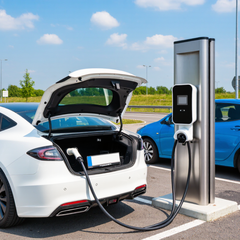
A CCS2 charging station is equipment designed to charge electric vehicles that use the Combined Charging System Type 2 connection. Its plug combines a Type 2-shaped upper section with two larger DC contacts below. Those contacts allow the station to supply direct current to a compatible vehicle. The station and vehicle communicate before charging begins, checking factors such as voltage and the battery’s charging limits.
The station’s purpose is to transfer energy safely and manage the charging session, not to guarantee a particular charging speed. Actual power depends on the station’s capacity, the vehicle’s limits, battery temperature, and its current state of charge. For example, a car arriving with a cold battery may initially accept less power, even at a high-capacity station.
The display may show the station’s maximum rating, but the vehicle often draws less. I find this detail easy to overlook when comparing chargers. A CCS2 station is therefore most useful when its connector and output suit the vehicle, and when its cable can reach the parking position comfortably.
A CCS2 charging station is more than a plug beside a parking bay. Its connector has a Type 2 section for AC charging and two larger contacts for DC power. A thick cable carries that power to the vehicle, while internal conductors also support control and communication. The cable can feel heavy, especially when it is cold or stiff. Small parts matter.
Inside the station, power electronics convert incoming electricity into the form needed for DC charging. Control systems communicate with the vehicle to agree on voltage and current limits before power flows. Safety components monitor conditions such as temperature, insulation faults, and unexpected current; contactors can disconnect the supply if a fault is detected. Some high-power units also use liquid cooling for cables and components. The exact layout varies by station, so a single diagram may not show every arrangement. In everyday use, the connector and screen get attention, but dependable charging also relies on sensors, software, and protective hardware working together. A missed detail here can cause trouble.
| Component | Role in the Charging System | Key Details |
|---|---|---|
| CCS2 vehicle connector | Connects the charging cable to a compatible vehicle inlet. | The Combo 2 connector combines the Type 2 interface with two larger contacts for DC charging. It supports AC charging through the Type 2 portion and DC charging through the dedicated DC contacts. |
| Vehicle inlet | Receives the connector and provides the electrical and communication interface on the vehicle. | A CCS2 vehicle inlet is designed for the corresponding Combo 2 connector. The vehicle’s onboard equipment determines the charging power it can accept. |
| Power conductors and contacts | Carry electrical power between the station and vehicle. | The upper Type 2 section includes AC power contacts and protective earth. The Combo 2 interface adds separate DC positive and negative contacts for DC charging. |
| Control Pilot (CP) | Supports control and communication between the charging equipment and the vehicle. | CP is used for functions such as indicating connection and charging states. CCS DC charging also uses communication over the control-pilot circuit. |
| Proximity Pilot (PP) | Helps detect the connector or cable connection and, where applicable, cable capability. | PP is part of the Type 2 connector interface. Its implementation and use depend on the connector and charging configuration. |
| Power conversion modules | Convert incoming AC electricity into controlled DC output for DC charging. | DC charging equipment typically uses power-electronic conversion stages. The number and rating of modules affect the station’s available output, subject to its design and operating conditions. |
| AC supply and protection | Connect the station to the electrical supply and help protect the equipment and installation. | Equipment may include switching, overcurrent protection, and other electrical protections selected for the installation and applicable requirements. |
| Contactors and switching devices | Connect or isolate the power path under the station’s control. | Switching devices are operated as part of the charging sequence and safety controls. They do not replace the protective devices required for the electrical installation. |
| Charging controller | Coordinates the charging process and manages station functions. | It handles functions such as the charging sequence, communication, monitoring, and control of power delivery according to the station’s design. |
| Communication system | Exchanges charging information between the vehicle and charging equipment. | CCS DC charging commonly uses power-line communication over the control-pilot path. Communication protocols can include DIN SPEC 70121 and ISO 15118, depending on implementation. |
| Cable and thermal management | Delivers power through the cable while keeping equipment within its operating limits. | Some high-power designs use liquid-cooled cables; others use different thermal designs. Cooling requirements vary with the station’s current rating and construction. |
| Metering and user interface | Provides charging information and, where fitted, records energy for operational or billing purposes. | Displays, payment facilities, and metering arrangements vary by station. Their presence does not change the CCS2 connector’s basic electrical interface. |
| Enclosure and safety systems | Protects internal equipment and supports safe operation in the intended environment. | The enclosure, monitoring, and safety features are selected for the installation. A CCS2 station must be designed and installed in accordance with applicable electrical and charging-equipment requirements. |
What Is a CCS2 Charging Station?
How CCS2 Charging Works
A CCS2 charging station uses a connector with a Type 2-shaped upper section and two large pins for direct current. After the plug clicks into place, the vehicle and charger exchange signals through the control pilot. They identify charging limits and confirm that the connection is safe before power flows. Communication commonly follows standards such as DIN SPEC 70121 or ISO 15118, depending on the vehicle and equipment.
The station converts grid power into DC and sends it to the battery, bypassing the car’s onboard AC charger. It adjusts voltage and current as the battery charges, while monitoring safety conditions. The actual rate depends on both the charger and the vehicle. Battery temperature and charge level matter, too. Not quite that simple. A cold battery, for example, may accept power more slowly even beside a high-capacity charger.
The IEA’s Global EV Outlook 2024 reports that public fast-charger stock grew by 55% worldwide in 2023. That growth makes clear communication and safe power control increasingly important. The handoff looks seamless on paper; in practice, vehicle limits and changing battery conditions can make charging less predictable. If a session slows near full charge, that is often battery management at work, not a faulty connection.
A CCS2 charging station uses the Combined Charging System connector, also called Combo 2. Its upper section follows the Type 2 design for AC charging; two larger contacts below carry DC power. This arrangement lets one vehicle inlet support both charging types. The plug may look familiar, but appearance alone does not confirm compatibility.
A vehicle needs a CCS2 inlet and compatible charging communication to use a CCS2 station for DC charging. In Europe and several other markets, many newer electric vehicles use this standard, but connector choices vary by model and region. Check the vehicle manual or inlet label before connecting. The station’s power rating matters too: a vehicle accepts only the power its onboard system can handle, even when the charger offers more. Charging speed also changes with battery temperature and state of charge.
The label alone can mislead. A Type 2-only vehicle may fit the AC portion of some equipment, yet it cannot use the station’s DC contacts without the required CCS2 hardware. Adapters are not universally suitable; use only equipment approved for the specific vehicle and charging setup. Standards and software can also affect a charging session, so a compatible plug does not guarantee every station will work smoothly. That detail is easy to overlook.
Power Levels, Safety, and Common Applications
A CCS2 charging station uses a connector designed for both AC and DC charging. Its upper section resembles a Type 2 plug, while two larger lower contacts carry DC power.
Power levels vary. Many public DC chargers provide about 50 to 350 kW, though some sites offer less. That rating is only a maximum. The vehicle’s charging limits, battery temperature, charge level, and available grid power all affect charging speed. A cold battery or one nearing full charge often accepts power more slowly.
Safety depends on more than a sturdy cable. Before charging begins, the vehicle and station exchange information and confirm a compatible connection. The system can monitor electrical faults, connector temperature, and locking status, then stop charging if readings fall outside safe limits.
Still, safeguards cannot fix a damaged cable or an obstructed connector. Check for cracked housings, unusual heat, or a plug that will not seat fully.
CCS2 stations commonly serve highway stops, public parking areas, workplaces, and fleet depots. I may be overly cautious, but a station’s uptime and vehicle compatibility matter as much as its advertised power.