Contract Manufacturing for Injection Molded Plastic Products in North America
(800) 824.0607
A molding machine transforms raw material into a shaped product through controlled heat, pressure, and motion. It may process plastic, rubber, metal, or composite materials, depending on its design. In a factory, the process can look simple: pellets enter a hopper, material softens inside a heated barrel, and a mold receives the prepared charge. The details matter.
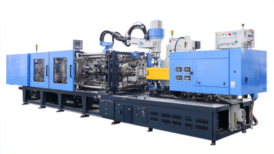
The machine then applies force to fill every cavity and hold the shape during cooling or curing. Clamping units keep the mold closed, while hydraulic or electric systems control movement with measured accuracy. Sensors monitor temperature, pressure, speed, and cycle time. Small errors matter. A few degrees of heat can change flow behavior, surface quality, or final strength.
Understanding how a molding machine works requires more than memorizing component names. It involves material science, mold design, machine maintenance, and practical production experience. Operators often inspect flash, short shots, sink marks, and uneven surfaces before adjusting settings. Engineers also review manufacturer specifications and recognized safety practices before changing a process. No machine behaves perfectly in every environment. Ambient temperature, material moisture, and tool wear can affect results. That is why reliable molding depends on controlled testing, accurate records, and careful observation. This guide explains the machine’s main parts, operating sequence, common molding methods, and factors that influence product quality. It also considers a practical question: why can two machines produce different results with the same mold and material?
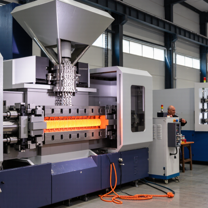
A molding machine shapes molten plastic inside a closed mold. The process includes clamping, injection, holding, cooling, and ejection. Its clamping force usually ranges from 5 to 6,000 ton-force. One ton-force equals approximately 9.81 kilonewtons. It describes mold-closing capacity, not machine weight.
Small 5–100-ton machines suit caps, medical parts, and compact housings. Larger systems handle automotive panels, pallets, and structural containers. Engineers estimate required force from projected part area, cavity pressure, material, and safety margin.
A simple rule can help. It can also mislead. Mold design, wall thickness, and injection speed change the real requirement.
The main core types are hydraulic, all-electric, and hybrid machines. Hydraulic systems provide strong force and broad process flexibility. Electric systems offer precise movement, repeatability, and lower idle energy use. Hybrid designs combine hydraulic clamping with electric injection or metering.
According to Grand View Research’s 2024 market report, the global injection molding machine market reached about USD 15.03 billion in 2023, with projected growth through 2030.
The Plastics Industry Association’s 2024 Size and Impact report also linked the United States plastics industry to roughly USD 548 billion in shipments during 2023.
These figures show market scale, but they do not replace machine trials. Temperature drift, recycled content, and operator settings still create variation. Even experienced teams should verify force calculations against actual parts and molds.
A molding machine turns heated plastic into a precise part through a controlled molding cycle. Granules enter the hopper and move through a rotating screw. Friction and barrel heaters melt the material into a consistent plastic melt. This stage is called plasticizing. Melt quality matters. Poor mixing can create streaks, weak areas, or uneven color.
During injection, the screw moves forward and pushes the melt into a closed mold. Pressure and speed must match the part’s geometry. Thin ribs may need faster filling, while deep sections can trap air. Packing follows injection. Extra pressure replaces material lost during shrinkage and helps preserve dimensions around holes, corners, and surfaces. Cooling then removes heat through channels inside the mold. Ejection begins only after the part has enough stiffness. Ejector pins release it without leaving severe marks or bending the part. In practice, a short cooling time may increase output, but it can also cause warping.
Tips: Watch the melt cushion, injection pressure, and actual mold temperature, not only the machine display. Check parts at the same interval during production. Measure weight and critical dimensions. Small changes often reveal trouble early. Keep a short process record. It exposes patterns that memory misses. A balanced cycle is rarely found in one attempt; material batches, ambient temperature, and mold wear can shift the result. That uncertainty deserves attention.
A molding machine converts polymer pellets into precise parts through heat, pressure, and controlled movement. According to PlasticsEurope’s Plastics—The Fast Facts 2023, global plastics production reached 400.3 million metric tonnes in 2022. That scale makes stable machine mechanics more than a production preference.
The screw L/D ratio means screw length divided by its diameter. A 20:1 ratio gives the polymer more time for melting, mixing, and pressure development than a shorter screw. However, longer is not always better. Excessive residence time can degrade heat-sensitive materials. I treat L/D as a starting point, not a guarantee. Injection pressure pushes the melt into the cavity, while holding pressure compensates for shrinkage during cooling. Too little pressure creates sinks or short shots. Too much can cause flash, stress, or difficult ejection.
Screw speed affects plasticizing time and shear heating. Faster rotation may improve output, but it can overheat the melt. Barrel temperature should follow the material supplier’s processing range, not guesswork. Mold temperature matters too; it controls cooling, surface quality, and dimensional stability. The International Energy Agency’s Energy Efficiency 2023 analysis identifies industrial process optimization as an important route for reducing energy demand. In practice, I would record melt temperature, actual pressure, cycle time, and part weight together. One setting can look successful while hiding unstable production. Small data gaps remain a problem.
| Machine Element / Variable | What It Means | Typical Data or Range | Effect on the Molding Process |
|---|---|---|---|
| Basic Machine Function | A molding machine melts polymer pellets, injects the melt into a closed mold, applies holding pressure, cools the part, and ejects it. | Main phases: plasticizing, mold closing, injection, holding, cooling, mold opening, and ejection. | Each phase influences part weight, dimensions, appearance, strength, and cycle time. |
| Injection Unit | The injection unit contains the hopper, heated barrel, reciprocating screw, nozzle, heaters, and drive system. | The screw both conveys and melts the material, then moves forward to inject it. | Stable feeding, melting, and injection are required for consistent shot-to-shot quality. |
| Clamping Unit | The clamping unit closes the mold and resists the force generated by cavity pressure. | Required clamp force depends on projected part area, cavity pressure, mold design, and safety margin. | Insufficient force may cause flash; excessive force can increase mold wear and energy use. |
| Screw L/D Ratio | L/D is the screw flighted length divided by the screw outside diameter. | General-purpose injection screws commonly use an L/D ratio of approximately 18:1 to 24:1. | A higher ratio generally provides more residence time and mixing, but may increase shear, heat history, and material degradation risk. |
| Screw Compression Ratio | This is the channel-depth ratio between the feed section and the metering section. | Common general-purpose values are approximately 2:1 to 4:1, depending on the polymer and screw design. | Higher compression can improve melting and mixing but may increase shear and melt temperature. |
| Screw Zones | The screw normally includes feed, transition or compression, and metering sections. | Typical approximate lengths are 40–50% feed, 20–30% transition, and 20–30% metering. | The zones progressively convey, compact, melt, mix, and homogenize the polymer. |
| Injection Pressure | Pressure applied to move molten polymer through the nozzle, runner, gate, and cavity. | Many applications operate around 70–140 MPa of plastic pressure; thin-wall or difficult-flow parts may require higher values. | Higher pressure improves filling ability but can increase flash, residual stress, clamp-force demand, and mold wear. |
| Holding or Packing Pressure | Pressure maintained after the cavity is filled to compensate for polymer shrinkage while the gate remains open. | A common starting point is approximately 30–70% of peak injection pressure, then adjusted by part quality. | Too little pressure may cause sink marks and low weight; too much may cause flash, warpage, or high stress. |
| Back Pressure | Resistance applied while the screw retracts during plasticizing. | Often set at a low-to-moderate level, commonly around 5–20% of the machine's maximum injection pressure, depending on the material. | It can improve melt uniformity and color dispersion, but excessive back pressure increases shear, heat, and cycle time. |
| Screw Speed | Rotational speed used to convey and melt pellets during the recovery stage. | A practical starting range for many applications is approximately 20–150 rpm, subject to screw diameter and resin limits. | Higher speed reduces recovery time but may increase shear heating, air entrainment, and degradation. |
| Injection Speed | The forward velocity of the screw while filling the mold. | Typical machine settings may range from approximately 10–300 mm/s; the correct value depends on part geometry and resin. | Higher speed can reduce premature freezing and weld-line visibility, but may increase shear, burn marks, and flash. |
| Barrel Temperature | Heater-zone settings that soften or melt the polymer before injection. | Typical melt-processing windows are roughly 180–320°C, depending on the resin; the manufacturer's processing range should control setup. | Low temperature can cause poor filling and high pressure; excessive temperature can cause degradation, flash, or discoloration. |
| Polymer Melt Temperature | The actual temperature of the molten polymer, which may differ from the barrel setpoint. | It is commonly checked against the resin's recommended processing window, often within approximately ±10–15°C of the target. | Melt temperature strongly affects viscosity, filling pressure, shrinkage, surface quality, and material residence-time sensitivity. |
| Mold Temperature | The temperature of the mold surfaces that contact the polymer. | Many commodity thermoplastics use approximately 20–80°C; engineering polymers may require higher temperatures. | It affects flow, gloss, crystallinity, weld lines, shrinkage, warpage, and demolding behavior. |
| Injection-to-Holding Changeover | The point at which the machine changes from velocity-controlled filling to pressure-controlled packing. | Common control methods include screw position, cavity pressure, hydraulic pressure, or a combination of these. | A stable changeover helps prevent short shots, over-packing, flash, and inconsistent part weight. |
| Cooling Time | The time required for the molded part to become rigid enough for ejection. | Cooling commonly represents approximately 40–70% of the total cycle, depending mainly on wall thickness and mold cooling. | Longer cooling reduces ejection deformation but lowers productivity; insufficient cooling can cause warpage and dimensional instability. |
| Cycle Time | The elapsed time from one mold-closing event to the next. | Many small and medium thermoplastic parts have cycles of approximately 10–60 seconds. | Cycle time is governed by filling, packing, cooling, screw recovery, mold movement, and ejection. |
| Shot Size | The total volume or mass of material prepared for one injection, including the molded parts, runners, and cushion. | The selected shot is commonly kept below the machine's maximum capacity; a working range of approximately 20–80% of rated shot size is often practical. | Very small or very large shots can increase residence time variation, melt degradation, or process instability. |
| Cushion | A small amount of melt remaining in front of the screw after injection and holding. | A common setup target is approximately 3–10 mm, depending on screw diameter and machine design. | A stable cushion supports consistent pressure transfer; zero cushion may indicate over-travel or unstable control. |
| Clamp Force Estimation | The force needed to keep the mold closed against cavity pressure. | A simplified estimate is: Clamp force = projected area × average cavity pressure, followed by an appropriate safety factor. | Accurate estimation prevents flash while avoiding unnecessary machine capacity and energy consumption. |
| Pressure–Speed–Temperature Relationship | These variables interact rather than operating independently. | Increasing melt temperature generally lowers viscosity; increasing speed raises shear rate and may generate additional heat. | Process optimization requires balancing filling speed, pressure, melt temperature, mold temperature, and cooling conditions. |
| Typical Process Sequence | A complete molding cycle follows a controlled sequence. | 1. Mold close → 2. Injection → 3. Holding → 4. Cooling and screw recovery → 5. Mold open → 6. Ejection. | Correct timing and repeatability are essential for stable production and consistent part quality. |
Note: The ranges shown are general engineering starting points. Actual settings must be validated using the specific polymer grade, mold design, part geometry, machine specifications, and material supplier recommendations.
A molding machine shapes heated plastic inside a prepared mold. The machine controls temperature, pressure, timing, and cooling. Operators load material, close the mold, and inspect each finished part. Small changes in moisture or temperature can create warping, short shots, or visible flow lines.
Injection molding melts plastic and pushes it into a closed mold under high pressure. It suits detailed parts, tight tolerances, and high production volumes. The cycle is quick, but the mold can be expensive and complex.
Blow molding forms hollow products by inflating a heated tube against the mold walls. It commonly produces bottles, tanks, and ducts. Wall thickness needs careful control.
Compression molding places a measured charge into an open mold. Heat and pressure then force the material into shape. This process works well for thicker components and thermoset materials. It usually uses lower pressure than injection molding, but cycle times may be longer.
Rotational molding heats plastic powder inside a rotating mold. The powder coats the inner surface as the mold turns on several axes. It creates large, hollow parts with relatively low tooling costs. Corners may be uneven.
No process wins every application. That matters. Choosing a method requires checking geometry, annual volume, surface finish, material behavior, and acceptable waste. In practice, production teams may discover that a theoretically ideal process performs poorly after cooling. Trial runs, measured samples, and documented settings provide more reliable decisions than assumptions alone.
An industrial molding machine heats material, injects it into a closed mold, and releases the formed part. ISO 20430 places safety at the center of this cycle. Operators should understand the machine’s hazards before production begins. Crushing points, hot surfaces, stored pressure, and unexpected movement require careful control. Keep hands away from the mold area.
Physical guards should prevent access to dangerous zones during operation. Interlocking devices should stop hazardous movement when a guard opens. Emergency stops must be visible, reachable, and regularly tested. They are not a substitute for proper guarding. A trained technician should verify their function during scheduled inspections.
Safe operation also depends on disciplined work habits. Before cleaning, adjustment, or maintenance, isolate electrical, hydraulic, and pneumatic energy according to the site procedure. Confirm zero movement before entering the mold area. Inspect hoses, cables, guards, and warning labels for damage. A small leak may become a serious failure. In practice, these checks are sometimes rushed, especially during a busy shift. That is a weakness worth correcting. Operators should record defects and report unclear instructions instead of relying on memory. ISO 20430 supports a structured approach, but real safety depends on competent people applying it consistently.