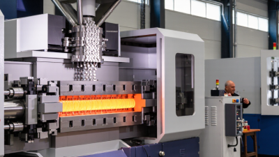
How to Choose a Small Injection Machine in 2026?
Choosing a small injection machine in 2026 is not simply a matter of finding the smallest press on the market. The right choice depends on the part, material, expected output, and available floor space. A compact machine may suit precision components, prototypes, or short production runs, but limited clamping force or shot capacity can quickly become a bottleneck. Small is relative.
Start with the part itself. Record its dimensions, weight, wall thickness, resin, and projected surface area. Then compare those requirements with the machine’s clamping force, injection capacity, tie-bar spacing, and mold thickness range. A mold that fits on paper may still leave too little room for safe installation or cooling connections. This detail is easy to overlook.
The machine’s controls and support matter as much as its specifications. Ask for material-specific cycle data, energy use, maintenance guidance, and service availability. If possible, test a representative mold and resin before committing. For a fair comparison, request the same performance details from each supplier; headline cycle times rarely tell the whole story. Some figures may still be estimates, so confirm them under your own production conditions.
This guide explains how to weigh those factors, compare electric and hydraulic options, and plan for future needs without buying excess capacity. A careful choice can save space and reduce operating costs. But there is no universal best machine: the right fit depends on what you actually make, and that deserves a second look.
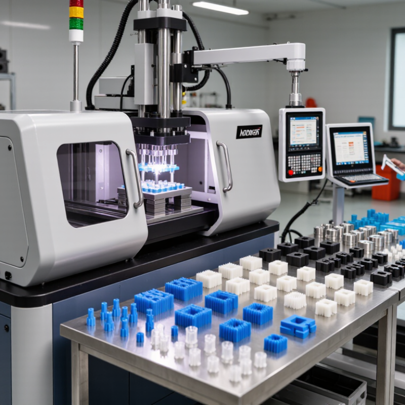
Define Part Size, Projected Area, and Material Before Machine Selection
A small part does not always require a small machine. Measure its length, width, and height, then check the largest molded envelope, including ribs and bosses. Small parts deceive. A thin, wide component may need more clamp force than a compact, thicker one. Also record the number of cavities and the runner layout; both add area and shot volume.
Projected area is the part’s silhouette facing the clamp, plus the runner’s projected area. Estimate clamp force from that total area and the material’s cavity pressure, then allow a suitable margin. The estimate is useful, not exact. Part geometry, flow length, and wall thickness can change pressure needs, so confirm the calculation with a mold or process specialist. Avoid choosing by tonnage alone.
Match the injection unit to the required shot weight, including runners, and keep the shot within the machine’s practical operating range. Too little capacity can cause short shots; an oversized barrel may hold material too long. Material matters here. Check viscosity, processing temperature, and drying requirements. Some resins absorb moisture quickly, so a dry-looking pellet is not proof of readiness. I would revisit these assumptions after reviewing sample parts and resin data; early estimates can be wrong.
Calculate Clamp Force at 2–5 US Tons per Square Inch of Projected Area
How to Choose a Small Injection Machine in 2026?
Estimate clamp force from the mold’s total projected area, measured perpendicular to the opening direction. Include every cavity and the runner system. A common starting range is 2–5 US tons per square inch, not a guaranteed setting. For example, a mold with 12 square inches of projected area suggests 24–60 tons. The wide range matters: resin, wall thickness, flow length, and injection conditions all affect the force needed to prevent flash. That estimate is useful, but not a promise.
Tips: Check the mold’s projected area from its parting-line view, then calculate both ends of the range. Confirm that the machine’s rated clamp force covers your chosen estimate. Also verify mold dimensions, tie-bar spacing, and shot capacity; a machine can meet the tonnage target and still be a poor fit.
Treat the calculation as a screening step. A thin-walled part or long flow path may need more clamp force than a simple, thick part. Review machine and mold specifications, then validate the setup with a cautious trial and inspect for flash or mold separation. I would not choose a machine from tonnage alone. One overlooked detail can change the fit.
How to Choose a Small Injection Machine in 2026?
Estimate clamp force using a preliminary rule of thumb of 2–5 US tons per square inch of projected area. Actual requirements depend on the resin, part geometry, mold design, and processing conditions.
How to read this chart: Multiply the projected area at the mold parting line, including runners, by 2 for the lower estimate and by 5 for the upper estimate. Confirm the final machine size with a qualified molding engineer.
Target a Shot Size of 20–80% of the Machine’s Rated Capacity
How to Choose a Small Injection Machine in 2026?
A useful starting point is to match the planned shot to 20–80% of the machine’s rated capacity. This range helps avoid running a machine near its limits or using only a tiny fraction of its capacity. If a part and its runner weigh 24 grams, a machine rated for roughly 30–120 grams may be worth evaluating. The exact fit depends on the resin and the machine’s rating method.
Stay within range.
Rated shot capacity is often stated using a specific reference material, so the number may not transfer directly to every resin. A denser or more viscous material can behave differently during plasticizing and injection. Check the machine manual, then confirm the material conversion with the supplier or a qualified process technician. Also include the runner and any expected cushion when estimating the shot—not just the finished part.
A shot near the low end may make metering less consistent, while a shot near the high end can leave little room for process adjustment. Neither outcome is automatic; screw design and material properties matter. I would treat 20–80% as a screening guide, not a guarantee. During trials, record shot weight, cushion, cycle stability, and visible defects. Measure twice. If the process window feels narrow, compare a different capacity before committing.
Match Injection Pressure and Screw Design to Resin Viscosity
Choosing a small injection machine in 2026 starts with the resin, not clamp size.
A low-viscosity grade may fill a thin cavity at modest pressure. A viscous grade may need more. Compare the mold’s pressure demand with the pressure available at the screw, not merely the machine’s advertised maximum. Confirm assumptions using the resin supplier’s processing data and a mold trial.
Screw design matters just as much.
A general-purpose screw suits many standard resins, but not every formulation. Glass-filled or shear-sensitive materials may require a different compression ratio, mixing section, or screw surface. For small parts, check that the shot uses a stable portion of the machine’s metering range. An oversized barrel can extend residence time and damage heat-sensitive resin. Not really a small detail.
Ask for the screw diameter, L/D ratio, check-ring design, and pressure specification. Then test the actual resin in the intended mold. Track fill time, cushion, melt temperature, and part weight over repeated cycles. If pressure rises while the cavity stays short, inspect drying, melt temperature, gate dimensions, and screw suitability before increasing machine size. Real trials can surprise you. A rule of thumb can mislead.
Check Mold Dimensions, Tie-Bar Spacing, Utilities, and Safety Requirements
How to Choose a Small Injection Machine in 2026?
A small machine still needs to fit the mold, not just the available floor space. Measure the mold’s width, height, and thickness, then compare them with platen size, daylight, and opening stroke. Include space for hoses and tool changes. A mold that fits on paper may still be awkward to install.
Check tie-bar spacing in both directions, and compare it with the mold’s outer dimensions. Allow room for clamps and locating rings. Check the machine’s ejector stroke and pattern, too; these details are easy to overlook when comparing clamp tonnage alone. A small mismatch can stop a job. Recheck the measurements against the machine drawing before ordering.
Utilities deserve the same attention. Confirm electrical supply, cooling-water flow, compressed-air needs, and any ventilation requirements at the planned location. Ask for actual consumption figures where available, rather than estimating from machine size. Then review fixed guards, door interlocks, emergency stops, and safe access for mold handling. Keep maintenance space clear. More capacity is not always better. A careful layout check can expose a practical issue early, though site conditions may still require a second review.
How to Choose a Small Injection Machine in 2026? — Check Mold Dimensions, Tie-Bar Spacing, Utilities, and Safety Requirements
Use this comparison as an early screening guide. Confirm every dimension and utility requirement against the machine and mold drawings before purchase or installation.
Small Injection Machine Selection Guide
| Selection factor |
Compact class |
General-purpose class |
Higher-capacity small class |
| Indicative clamp force |
About 30 metric tons (294 kN) |
About 60 metric tons (588 kN) |
About 100 metric tons (981 kN) |
| Indicative tie-bar spacing, W × H |
260 × 230 mm (10.2 × 9.1 in) |
320 × 290 mm (12.6 × 11.4 in) |
410 × 370 mm (16.1 × 14.6 in) |
| Indicative platen size |
About 400 × 400 mm (15.7 × 15.7 in) |
About 500 × 500 mm (19.7 × 19.7 in) |
About 600 × 600 mm (23.6 × 23.6 in) |
| Indicative mold thickness range |
150–300 mm (5.9–11.8 in) |
180–380 mm (7.1–15.0 in) |
220–450 mm (8.7–17.7 in) |
| Indicative maximum daylight |
About 450 mm (17.7 in) |
About 550 mm (21.7 in) |
About 650 mm (25.6 in) |
| Indicative shot capacity |
About 60 g polystyrene equivalent |
About 130 g polystyrene equivalent |
About 250 g polystyrene equivalent |
| Initial shot-size check |
Approximately 12–48 g, using 20–80% of nominal capacity |
Approximately 26–104 g, using 20–80% of nominal capacity |
Approximately 50–200 g, using 20–80% of nominal capacity |
| Mold-fit checks |
Verify mold width and height clear the tie bars; check mold thickness against the machine adjustment range; confirm locating-ring, nozzle, ejector, clamp-slot, and lifting clearances. Include runners and sprues when estimating shot size. |
| Indicative connected electrical load |
About 15–25 kW |
About 25–45 kW |
About 40–70 kW |
| Electrical supply to confirm |
Match the machine nameplate and site supply. Three-phase voltage and frequency vary by region; confirm breaker, cable, grounding, phase sequence, and any transformer requirements with a qualified electrician. |
| Cooling-water planning range |
About 5–15 L/min |
About 10–25 L/min |
About 15–35 L/min |
| Cooling and compressed-air checks |
Confirm required water temperature, pressure, flow, hose connections, and heat-removal capacity for both machine and mold. If pneumatic equipment is used, verify its required air pressure and flow from the equipment specifications. |
| Floor and handling checks |
Allow room for mold changes, material loading, operator access, guarding, and maintenance. Check machine mass, floor loading, door and aisle clearances, and the capacity and reach of lifting equipment. |
| Safety requirements |
Confirm applicable local regulations and the current machine-safety standard for the installation. Check fixed and interlocked guards, safe mold-area access, emergency stops, electrical isolation, documented operating procedures, and required operator training. ISO 20430 is an international safety standard for injection molding machines; verify the applicable edition and local adoption. |
| Before final selection |
Compare the actual mold drawing and projected area with the machine’s clamp-force calculation, platen layout, tie-bar spacing, daylight, opening stroke, ejector stroke, and injection-unit specifications. Obtain written confirmation of all dimensions and utility requirements for the exact configuration. |
Note: Machine-class figures are representative planning estimates, not guaranteed specifications. Actual dimensions, capacities, power, and cooling requirements vary by machine design, screw and barrel configuration, mold, resin, and operating conditions.